


P070/P071/P085/P086/P100/P101
5-2
5
Operation
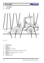
Figure 5-1
5
Operation
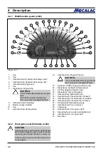
5.1
Checks before start-up
- Engine oil level (see the operating instructions for the engine)
- Brake fluid (brake hydraulic oil)
- Hydraulic oil level
- Fuel level
- Tyre pressure
- Profile depth
- Lighting system
- Seat position
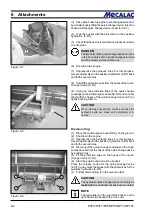
- Remove the lock levers for the auxiliary and working
hydraulics pilot valves (4-8/6) if present
» only if work is to be commenced «
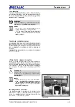
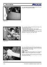
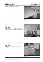
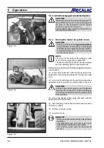
- Bucket arm prop [(e.g. bucket arm support (option)
(1-2/arrow)]; remove if necessary
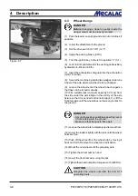
- Articulation safeguard (1-3/arrow); remove if necessary
- General state of the loader, e.g. check for leaks
- The presence of
- a fist aid kit
- a warning triangle
- a signal lamp
must be verified.
5.2
Start-up
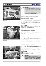
5.2.1
Starting the diesel engine
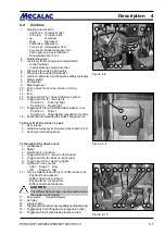
(1) Apply the parking brake (4-9/3).
(2) Set the drive switch (4-10/11) to “0” (starter interlock!).
(3) Turn the main battery switch (8-36/1) clockwise to the
stop.
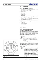
(4) Insert the ignition key into the starter switch (4-8/7)
and turn the key clockwise to position "II“ (5-1).
NOTE
- Indicators for battery charge, parking brake,
engine oil pressure and preheating light up. The
fuel gauge, the coolant temperature gauge, the
operating hour counter and the digital clock
function.
- Start the engine in position "0“ of the drive
switch (4-10/11).
(5) Turn the ignition key clockwise to position "III“ (5-1)
after a few seconds (preheating). As soon as the engine
starts, release the ignition key.
NOTE
- If the engine has not started after two attempts,
determine the cause using the malfunction table
in the operating instructions for the engine.
- For operation at extremely low temperatures,
see the operating instructions for the engine.
- Run the engine at a low speed and do not subject
it to full load until the hydraulic oil has reached its
operating temperature after a cold start.
When a hydraulic oil filter clogging indicator
(4-11/13) (option) is present, it will go out as soon
as the hydraulic oil has reached its operating
temperature.
Summary of Contents for AX 1000
Page 9: ...Safety regulations...
Page 21: ...Signs...
Page 24: ......
Page 25: ...Protectionagainsttheft...
Page 28: ......
Page 29: ...Description...
Page 43: ...Operation...
Page 53: ...Attachments...
Page 58: ......
Page 59: ...Rescue towing lashing lifting by crane...
Page 66: ......
Page 67: ...Maintenance...
Page 83: ...Faults causes and remedies...
Page 86: ......
Page 87: ...Circuit diagrams...
Page 97: ......
Page 100: ......
Page 101: ...Technical data loader...
Page 111: ...Technical data attachments...
Page 124: ......
Page 125: ...Additional options modifications Notes on inspection for loaders...
Page 127: ...P070 P071 P085 P086 P100 P101 13 3 Additionaloptions modfications 13...
Page 128: ...P070 P071 P085 P086 P100 P101 13 4 13 Additionaloptions modfications...
Page 129: ...P070 P071 P085 P086 P100 P101 13 5 Additionaloptions modfications 13...
Page 130: ...P070 P071 P085 P086 P100 P101 13 6 13 Additionaloptions modfications...
Page 131: ...P070 P071 P085 P086 P100 P101 13 7 Additionaloptions modfications 13...
Page 132: ...P070 P071 P085 P086 P100 P101 13 8 13 Additionaloptions modfications...
Page 133: ...P0700 P0710 P0850 P0860 P1000 P1010 Index i Index...
Page 134: ...P0700 P0710 P0850 P0860 P1000 P1010 Index ii Index...
Page 135: ...P0700 P0710 P0850 P0860 P1000 P1010 Index iii Index...
Page 136: ...P0700 P0710 P0850 P0860 P1000 P1010 Index iv Index...
Page 137: ...P0700 P0710 P0850 P0860 P1000 P1010 Index v Index...
Page 138: ...P0700 P0710 P0850 P0860 P1000 P1010 Index vi Index...
Page 139: ...P0700 P0710 P0850 P0860 P1000 P1010 Index vii Index...
Page 140: ...P0700 P0710 P0850 P0860 P1000 P1010 Index viii Index...
Page 141: ...P0700 P0710 P0850 P0860 P1000 P1010 Index ix Index...
Page 142: ...P0700 P0710 P0850 P0860 P1000 P1010 Index x Index...
Page 143: ...P0700 P0710 P0850 P0860 P1000 P1010 Index xi Index...
Page 144: ...P0700 P0710 P0850 P0860 P1000 P1010 Index xii Index 23128003 Index 0...


