P070/P071/P085/P086/P100/P101
5-6
5
Operation
2
1
4
3
1
2
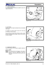
Figure 5-6
Figure 5-8
Figure 5-7
CAUTION
- The hydraulic quick-change device must only
be locked if an attachment has been mounted.
- If the hydraulic oil temperature indicator lamp
(4-11/14) lights up during operation, the loader
must be switched off immediately, the cause
must be determined by a hydraulics expert and
the malfunction must be eliminated.
5.2.5
Heating and ventilation system
5.2.5.1 Setting the air flow
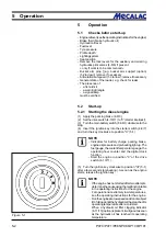
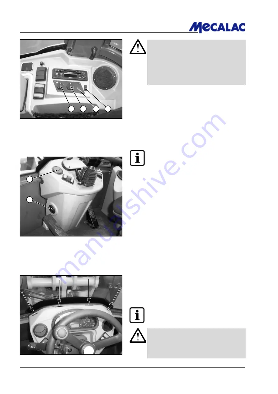
(1) Turn the rotary switch (5-6/1) for the blower to position
0, 1, 2, or 3 depending on the air flow desired.
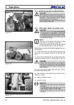
(2) Set the air flow direction with the air outlet nozzles to
the right and left of the steering column/dashboard (5-7/1
and 5-7/2).
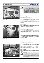
NOTE
There are also four invariable air nozzles in the
windshield area (5-8/arrows).
5.2.5.2 Switching on the heater
(1) Turn the knob (5-6/2) in the clockwise (cold) or the
anti-clockwise direction (warm) to reach the desired
temperature.
5.2.5.3 Switching on the air condition (opt.)
(1) Press the „ON/OFF“ switch (5-6/4) to control the air
condition as desired.
Switch pressed in the upper half
- Air condition "OFF“
Switch pressed in the lower half
- Air condition "ON“
5.2.5.4 Setting the temperature
(1) The rotary switch (5-6/3) lets you control the tempera-
ture in the driver’s cabin.
Rotary switch in clockwise direction
- colder
Rotary switch in counter clockwise direction - warmer
NOTE
The air condition is supplied via an air opening
behind the driver’s seat.
CAUTION
For safety instructions and pertaining disposal
regulations as well as for maintenance information,
refer to the operating instructions that come with
the air condition.
Summary of Contents for AX 1000
Page 9: ...Safety regulations...
Page 21: ...Signs...
Page 24: ......
Page 25: ...Protectionagainsttheft...
Page 28: ......
Page 29: ...Description...
Page 43: ...Operation...
Page 53: ...Attachments...
Page 58: ......
Page 59: ...Rescue towing lashing lifting by crane...
Page 66: ......
Page 67: ...Maintenance...
Page 83: ...Faults causes and remedies...
Page 86: ......
Page 87: ...Circuit diagrams...
Page 97: ......
Page 100: ......
Page 101: ...Technical data loader...
Page 111: ...Technical data attachments...
Page 124: ......
Page 125: ...Additional options modifications Notes on inspection for loaders...
Page 127: ...P070 P071 P085 P086 P100 P101 13 3 Additionaloptions modfications 13...
Page 128: ...P070 P071 P085 P086 P100 P101 13 4 13 Additionaloptions modfications...
Page 129: ...P070 P071 P085 P086 P100 P101 13 5 Additionaloptions modfications 13...
Page 130: ...P070 P071 P085 P086 P100 P101 13 6 13 Additionaloptions modfications...
Page 131: ...P070 P071 P085 P086 P100 P101 13 7 Additionaloptions modfications 13...
Page 132: ...P070 P071 P085 P086 P100 P101 13 8 13 Additionaloptions modfications...
Page 133: ...P0700 P0710 P0850 P0860 P1000 P1010 Index i Index...
Page 134: ...P0700 P0710 P0850 P0860 P1000 P1010 Index ii Index...
Page 135: ...P0700 P0710 P0850 P0860 P1000 P1010 Index iii Index...
Page 136: ...P0700 P0710 P0850 P0860 P1000 P1010 Index iv Index...
Page 137: ...P0700 P0710 P0850 P0860 P1000 P1010 Index v Index...
Page 138: ...P0700 P0710 P0850 P0860 P1000 P1010 Index vi Index...
Page 139: ...P0700 P0710 P0850 P0860 P1000 P1010 Index vii Index...
Page 140: ...P0700 P0710 P0850 P0860 P1000 P1010 Index viii Index...
Page 141: ...P0700 P0710 P0850 P0860 P1000 P1010 Index ix Index...
Page 142: ...P0700 P0710 P0850 P0860 P1000 P1010 Index x Index...
Page 143: ...P0700 P0710 P0850 P0860 P1000 P1010 Index xi Index...
Page 144: ...P0700 P0710 P0850 P0860 P1000 P1010 Index xii Index 23128003 Index 0...

