P070/P071/P085/P086/P100/P101
7-5
Rescue, towing,
7
lashing, lifting by crane
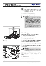
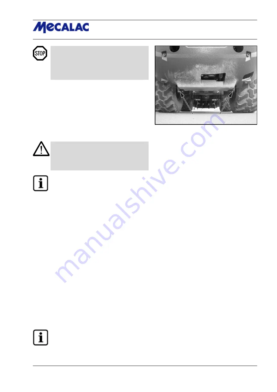
Figure 7-7
- The max. permissible load of the shunting and
towing coupling (7-2/2) is 4.5 t horizontally in
the longitudinal direction.
- The max. permissible load of the lashing/load-
bearing points (7-6/arrows, and 7-7/arrows) is
2.0 t.
7.1.1.2 Towing the articulated loader when
the traction drive has failed
(1) Actuate the toggle switch for the hazard flasher (4-8/13).
(2) Set the drive switch (4-10/11) to “0”.
(3) Apply the parking brake (4-9/3).
CAUTION
If the rescue location is on an uphill/downhill grade,
wheel chocks must be placed on the sloping side of
both front axle wheels in addition to applying the
parking brake.
NOTE
The preparations described in steps (4) and (5)
are only to be carried out if the rescue location
is
not
on a public road:
(4) Cover the bucket cutting edge and teeth with the
bucket protector (5-4/arrow).
(5) Insert the plug of the bucket protector into the socket
(5-5/arrow, option).
(6) Lift and mechanically prop up bucket arm [e.g. by
inserting the bucket arm support (option) (1-2/arrow)] and
lower bucket arm until it rests on the bucket arm support by
actuating the lever for the working hydraulics (4-8/4).
(7) Lock the pilot valves for working and auxiliary hydrau-
lics (1-2/arrow) (rear position).
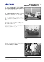
(8) Connect the tow rod to the loader to be towed (7-2/
arrow) and to the towing vehicle.
(9) Undo the fastening screw on the hydraulic oil tank
(7-3/arrow) of the right rear mudguard.
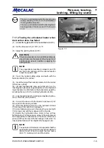
(10) Undo fastening screws in the wheel house rear right
(7-4/arrows) and pull the mudguard off to the side.
(11) Switch the hydrostatic drive motor to free oil flow
before towing. For this purpose, screw in the setscrews at
both high pressure relief valves (7-5/arrows) of the drive
pump until they are level with the hexagon nuts (size 13)
loosened beforehand. Then tighten the hexagon nuts.
NOTE
The operator of the loader is responsible that the
(optional) tool required to remove the mudguard
(items 9 and 10) and to adjust the drive pump
(item 11) is always on board the loader.
Summary of Contents for AX 1000
Page 9: ...Safety regulations...
Page 21: ...Signs...
Page 24: ......
Page 25: ...Protectionagainsttheft...
Page 28: ......
Page 29: ...Description...
Page 43: ...Operation...
Page 53: ...Attachments...
Page 58: ......
Page 59: ...Rescue towing lashing lifting by crane...
Page 66: ......
Page 67: ...Maintenance...
Page 83: ...Faults causes and remedies...
Page 86: ......
Page 87: ...Circuit diagrams...
Page 97: ......
Page 100: ......
Page 101: ...Technical data loader...
Page 111: ...Technical data attachments...
Page 124: ......
Page 125: ...Additional options modifications Notes on inspection for loaders...
Page 127: ...P070 P071 P085 P086 P100 P101 13 3 Additionaloptions modfications 13...
Page 128: ...P070 P071 P085 P086 P100 P101 13 4 13 Additionaloptions modfications...
Page 129: ...P070 P071 P085 P086 P100 P101 13 5 Additionaloptions modfications 13...
Page 130: ...P070 P071 P085 P086 P100 P101 13 6 13 Additionaloptions modfications...
Page 131: ...P070 P071 P085 P086 P100 P101 13 7 Additionaloptions modfications 13...
Page 132: ...P070 P071 P085 P086 P100 P101 13 8 13 Additionaloptions modfications...
Page 133: ...P0700 P0710 P0850 P0860 P1000 P1010 Index i Index...
Page 134: ...P0700 P0710 P0850 P0860 P1000 P1010 Index ii Index...
Page 135: ...P0700 P0710 P0850 P0860 P1000 P1010 Index iii Index...
Page 136: ...P0700 P0710 P0850 P0860 P1000 P1010 Index iv Index...
Page 137: ...P0700 P0710 P0850 P0860 P1000 P1010 Index v Index...
Page 138: ...P0700 P0710 P0850 P0860 P1000 P1010 Index vi Index...
Page 139: ...P0700 P0710 P0850 P0860 P1000 P1010 Index vii Index...
Page 140: ...P0700 P0710 P0850 P0860 P1000 P1010 Index viii Index...
Page 141: ...P0700 P0710 P0850 P0860 P1000 P1010 Index ix Index...
Page 142: ...P0700 P0710 P0850 P0860 P1000 P1010 Index x Index...
Page 143: ...P0700 P0710 P0850 P0860 P1000 P1010 Index xi Index...
Page 144: ...P0700 P0710 P0850 P0860 P1000 P1010 Index xii Index 23128003 Index 0...


