P070/P071/P085/P086/P100/P101
7-6
7
Rescue, towing,
lashing, lifting by crane
D
A
2
C
2
D
B
A
1
C
1
1
2
1
2
NOTE
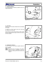
After towing has been completed, loosen the
hexagon nuts again. Screw the setscrews out of
both high-pressure relief valves until they stop
and tighten the lock nuts.
(12) Remove the chocks (if applicable).
(13) Release the parking brake (4-9/3).
DANGER
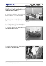
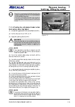
- With the engine running, tow the loader at
walking speed (2 km/h).
- The towing distance should not exceed 1 km.
- For a longer distance, the defective loader must
be loaded onto a truck (for the lashing points,
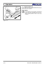
see 7-2/arrow, 7-7/6/arrows and 7-7/arrows).
- The max. permissible load of the shunting and
towing coupling (7-2/2) is 4.5 t horizontally in
the longitudinal direction.
- The max. permissible load of the lashing/load-
bearing points (7-6/arrows, and 7-7/arrows) is
2.0 t.
7.2
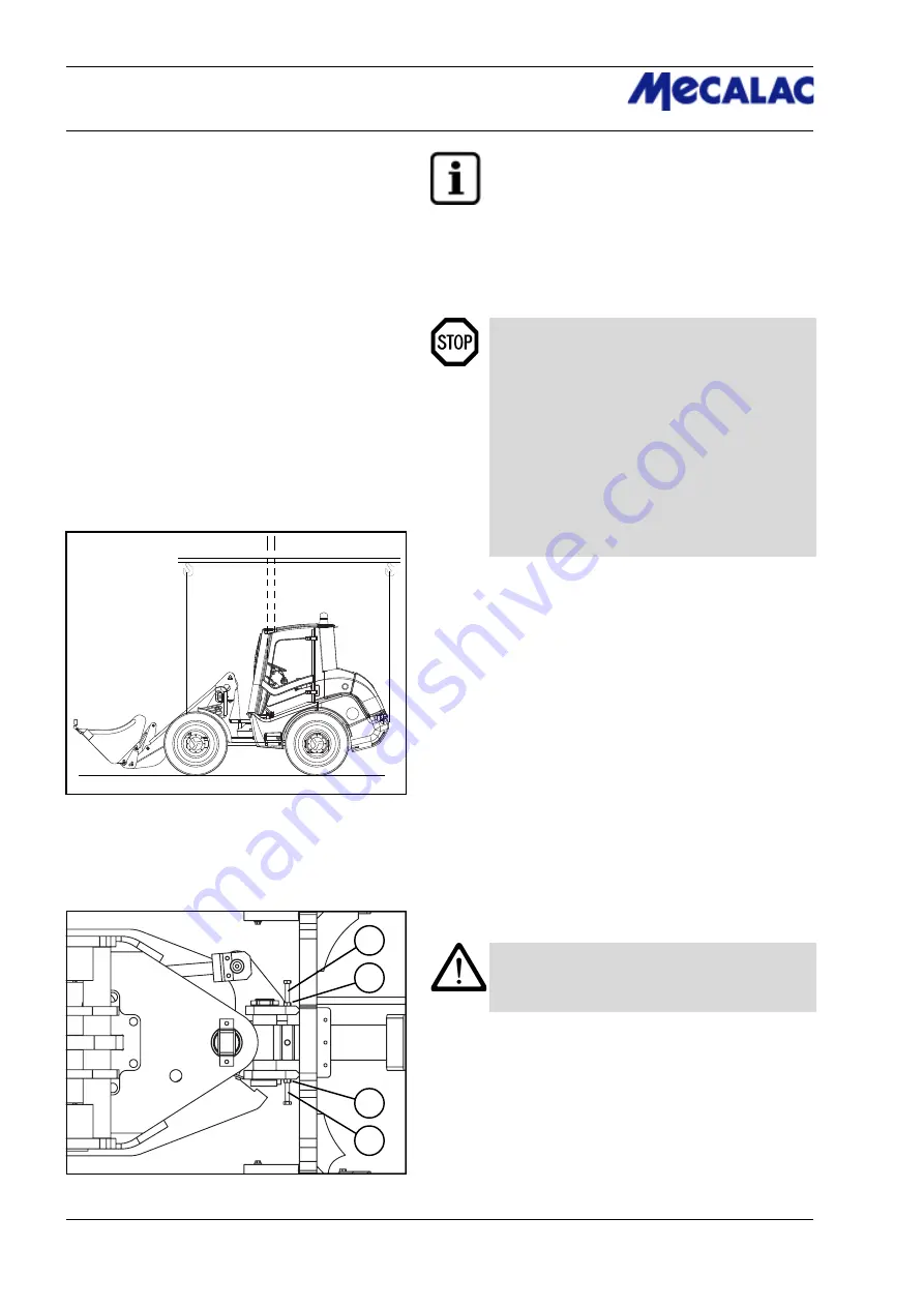
Lifting by crane
The loader to be lifted must be prepared as follows:
(1) Set the drive switch (4-10/11) to “0”.
(2) Set hydraulic drive stage „I“ (4-10/9).
(3) Apply the parking brake (4-9/3).
(4) Lift or lower the bucket arm until the lowest point of the bucket
arm or of the bucket is at least 30 cm above the road (5-4).
(5) Close the pilot valve for the working and auxiliary
hydraulics (1-2/arrow).
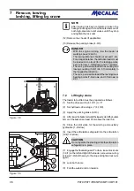
(6) Insert the articulation safeguard into the articulation
joint (1-3/arrow).
CAUTION
Do not operate the steering while the articulation
safeguard is in place.
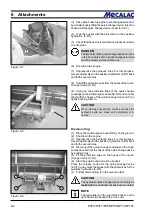
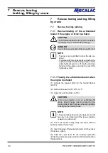
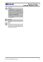
(7) Engage the float safeguard. To do so, loosen lock nuts
(7-9/1) on the left and right of the loader, screw in securing
screws (7-9/2) all the way to the stop and tighten lock nuts
again.
(8) Lock both doors.
(9) Fold the outside mirror inwards.
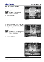
Figure 7-8
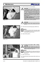
Figure 7-9
Summary of Contents for AX 1000
Page 9: ...Safety regulations...
Page 21: ...Signs...
Page 24: ......
Page 25: ...Protectionagainsttheft...
Page 28: ......
Page 29: ...Description...
Page 43: ...Operation...
Page 53: ...Attachments...
Page 58: ......
Page 59: ...Rescue towing lashing lifting by crane...
Page 66: ......
Page 67: ...Maintenance...
Page 83: ...Faults causes and remedies...
Page 86: ......
Page 87: ...Circuit diagrams...
Page 97: ......
Page 100: ......
Page 101: ...Technical data loader...
Page 111: ...Technical data attachments...
Page 124: ......
Page 125: ...Additional options modifications Notes on inspection for loaders...
Page 127: ...P070 P071 P085 P086 P100 P101 13 3 Additionaloptions modfications 13...
Page 128: ...P070 P071 P085 P086 P100 P101 13 4 13 Additionaloptions modfications...
Page 129: ...P070 P071 P085 P086 P100 P101 13 5 Additionaloptions modfications 13...
Page 130: ...P070 P071 P085 P086 P100 P101 13 6 13 Additionaloptions modfications...
Page 131: ...P070 P071 P085 P086 P100 P101 13 7 Additionaloptions modfications 13...
Page 132: ...P070 P071 P085 P086 P100 P101 13 8 13 Additionaloptions modfications...
Page 133: ...P0700 P0710 P0850 P0860 P1000 P1010 Index i Index...
Page 134: ...P0700 P0710 P0850 P0860 P1000 P1010 Index ii Index...
Page 135: ...P0700 P0710 P0850 P0860 P1000 P1010 Index iii Index...
Page 136: ...P0700 P0710 P0850 P0860 P1000 P1010 Index iv Index...
Page 137: ...P0700 P0710 P0850 P0860 P1000 P1010 Index v Index...
Page 138: ...P0700 P0710 P0850 P0860 P1000 P1010 Index vi Index...
Page 139: ...P0700 P0710 P0850 P0860 P1000 P1010 Index vii Index...
Page 140: ...P0700 P0710 P0850 P0860 P1000 P1010 Index viii Index...
Page 141: ...P0700 P0710 P0850 P0860 P1000 P1010 Index ix Index...
Page 142: ...P0700 P0710 P0850 P0860 P1000 P1010 Index x Index...
Page 143: ...P0700 P0710 P0850 P0860 P1000 P1010 Index xi Index...
Page 144: ...P0700 P0710 P0850 P0860 P1000 P1010 Index xii Index 23128003 Index 0...


