background image

NEED HELP? 1-800-832-2966


16 


Starting the Tiller 

The controls required to start and run the tiller are located on the engine and are marked with the 
icons for choke, slow and fast for the throttle, and on/off for the fuel valve. 


Starting a Cold Engine 

1)  Turn the engine s

witch to the “on” position. 

2)  Move the fuel v

alve lever to the “on” position. 

3)  Move choke l

ever to the left for full choke, the “start” position. 

4)  Move throttle control 

lever to “start” or “fast” position. 

5)  Pull starting cord out slowly one time and allow to return normally, maintaining control of the starter cord at all 

times, do not allow it to “snap back”. 

6)  Pull starter cord rapidly, and allow rope to return normally, maintaining control of the starter cord at all times, 

do not allow it to “snap back”.  Repeat until the engine starts. 

7) 

When the engine starts, gradually move the choke lever to the “run” position and adjust the throttle to the 
desired speed. 

8)  Normal throttle position for best 

machine operation will be the “fast” position. 


Restarting a Warm Engine 

1)  Normally a warm engine will not require the use of the choke. 

2)  Turn the engine switch as well as the fuel valve lever 

to the “on” position. 

3)  Move the throttle control 

lever to the “start” or “fast” position. 

4)  Pull starter cord rapidly, and allow rope to return normally, maintaining control of the starter cord at all times, 

do not allow it to “snap back”. Repeat until the engine starts. 

5)  Normal throttle position for best machine operation w

ill be the “fast” position. 


USING THE MACHINE 


Although reading this manual and the safety instructions it contains will provide you with the necessary basic 
knowledge to operate this equipment safely and effectively, we have placed several safety labels on the tiller to 
remind you of this important information while you are operating the unit. 
 
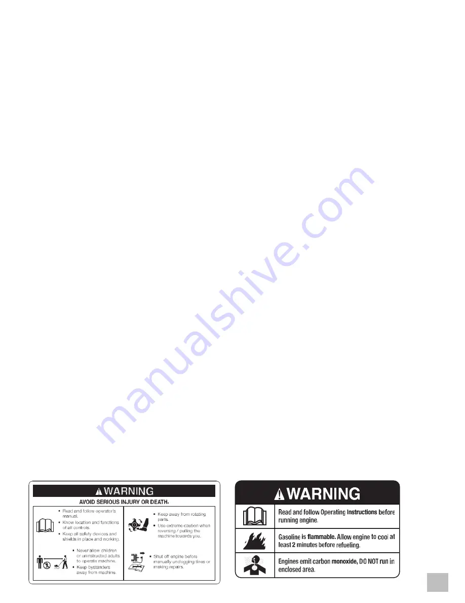
These important safety labels are shown here to help familiarize you with the operational and safety messages 
you will see as you perform normal tilling operations. Please review these labels now. If you have any 
questions regarding their meaning or how to comply with these instructions, reread the complete safety 
instruction text on the preceding pages, or contact us at 1-800-832-2966 for any questions. 


Summary of Contents for MM212RTT

Page 1: ...e right to change this product at any time without prior notice IF THERE IS ANY QUESTION ABOUT A CONDITION BEING SAFE OR UNSAFE DO NOT OPERATE THIS PRODUCT DO NOT RETURN THIS REAR TINE TILLER TO THE R...

Page 2: ...ell the exhaust you could be breathing CO CALIFORNIA PROPOSITION 65 WARNING This product or the exhaust from this product may contain chemicals known to the State of California to cause cancer birth d...

Page 3: ...lebars lower 13 Handlebars upper 13 Front Guard 13 PREPARING THE MACHINE FOR USE 14 Using this Machine for the First Time 14 STARTING THE MACHINE 15 Pre Start Inspection 15 Starting the Tiller 16 USIN...

Page 4: ...ve the forward drive belt 24 To remove the reverse drive belt 24 To install the reverse drive belt 24 To install the forward drive belt 24 Cleaning the Machine 25 STORAGE PROCEDURES 25 TROUBLESHOOTING...

Page 5: ...ded may result in property damage Safety Warning Symbols The following symbols may be present on your machine Carefully read and understand their meaning Look for this symbol to point out important sa...

Page 6: ...eas Keep at least several feet of clearance on all sides to allow for proper ventilation for this machine High Temperatures This machine produces heat when in operation Temperatures near the exhaust c...

Page 7: ...and other safety items in place and working correctly Service the unit only with authorized or approved replacement parts Complete all unit maintenance and adjustments according to the instructions i...

Page 8: ...orts DO NOT wear loose clothing which could get caught in this equipment Always wear work gloves and sturdy footwear such as leather work shoes or short boots These will protect ankles and shins from...

Page 9: ...epairing or inspecting the unit Make sure all moving parts have stopped Let the engine cool disconnect the spark plug wire and move it away from the spark plug Keep the tiller in safe working conditio...

Page 10: ...included STOP If there are missing items call 1 800 832 2966 Monday Friday 9 AM 6 PM Central Time for customer service DO NOT RETURN THIS MACHINE TO THE RETAILER Item List 2 Wheel retainer pins 1 Dep...

Page 11: ...d Control Lever 7 Fuel Valve 13 Wheel 2 Reverse Control Lever 8 Throttle Control 14 Wheel Locking Pin 3 Fuel Tank 9 Recoil Starter 15 Tines 4 Spark Plug 10 Engine Switch 16 Tine Debris Shield 5 Air Fi...

Page 12: ...ctional Ensure the tread faces as shown for best performance 3 Slide the wheel hub onto the wheel axle 4 To engage in tilling mode ensure the hub hole aligns with the hole in the axle and insert the l...

Page 13: ...embly down onto the lower handle 2 Align the bolt holes and insert the saddle bolts and secure with the handle knobs 3 Secure the cables to the handlebars using cable ties Front Guard 1 Install the fr...

Page 14: ...with an API rating of SG SH SJ or higher Model MM212RTT Oil Capacity 17 0 Ounces Oil Type Recommended SAE10W 30 To check add oil 1 Confirm that the machine is on a level surface Set the depth regulato...

Page 15: ...ly Check position of wheels ensure in the tilling mode and secure the wheel locking pins Check depth regulator lever position Ensure tines are clear of the ground before starting Examine underneath an...

Page 16: ...ing a Warm Engine 1 Normally a warm engine will not require the use of the choke 2 Turn the engine switch as well as the fuel valve lever to the on position 3 Move the throttle control lever to the st...

Page 17: ...o typically slow the forward movement when tilling by applying slight downward pressure on the handlebars 5 Raise the depth regulator one step at a time to till more deeply It is always best to make m...

Page 18: ...and allow the machine to do the work Always press the forward or reverse drive levers down completely onto the handle bar Failure to do so may result in excessive drive belt wear and premature drive...

Page 19: ...ve the lock pin 2 Align the hole in axle with the hole in the wheel hub 3 Insert the lock pin through both wheel and axle 4 Fold lock pin ring to secure the pin to axle 5 Ensure the wheel is firmly lo...

Page 20: ...s will allow for shallow tilling With the depth regulator in this position make several light passes over the area to be tilled Reset for deeper depths with successive passes If tiller jumps or skids...

Page 21: ...Every 25 Hours of Use After Every 50 Hours of Use After Every 100 Hour of Use Before Each Season Before Storage See Note Below Check air pressure in tires Check Engine Oil Level Fill to Proper Level...

Page 22: ...ace oil level dipstick in the filler hole Note that the drive wheel transmission and rear tine transmission are one common reservoir When you add oil you must wait a short period of time for the oil t...

Page 23: ...ior to further disassembly Remove the air filter assembly Carefully remove the foam pre filter Clean the foam pre filter with mild soap and water Rinse foam pre filter well gently squeeze out excess w...

Page 24: ...oop of the belt around the forward portion of the transmission pulley Replace the reverse belt idler into the reverse belt idler bracket and against not around the engine pulley Be sure the belt is in...

Page 25: ...y o Keep out of reach of children and pets Drain the fuel o Turn the engine switch to Off and allow the engine to cool completely o Drain all gasoline from the fuel tank by loosening the carburetor dr...

Page 26: ...k engine oil Add or drain engineoil if necessary 3 Remove spark plug andinspect Replace if necessary 4 Remove and clean air filter 5 Drain fuel tank Clean fuel tank Fill withfresh fuel 6 Take unit to...

Page 27: ...tilling depth Power Output 4 2kW 5 6hp Easy recoil start Torque 12 5Nm 2500rpm Pistol grip handles Fuel Type Gasoline Counter rotating tines Fuel Capacity 3 1L 82gal 5 Position depth adjustment Fuel E...

Page 28: ...incidental or consequential damages Some states do not allow limitation on the length of an implied warranty QJ North America Inc will repair or replace at its discretion any part that is proven to be...

Reviews: