10
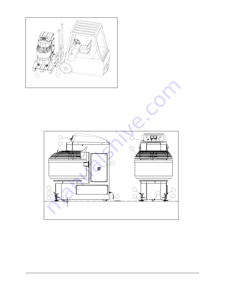
Pict. 2.2
Remove the docking device Pos. 2, introduce
the lifting forks Pos.4 as shown in Pict. 2.2 and
carefully lift the machine.
2.3
ADJUSTMENTS
After positioning in the selected area, adjust the front leveling feet Pos.51 Pict.2.3 with the3 lobe handwheel
Pos. 53 to get perfect leveling and then lock it by tightening the nut Pos. 52.
If the machine is unstable due to floor irregularity, adjust the support feet or wheels by inserting rubber pieces.
2.4
ELECTRICAL CONNECTIONS
The machine is equipped with connecting cable located on the back of the machine. It’s essential to mount a
normalised and polarised plug at the end of the cable.
1
51
53
52
4
2
3
2
4
51
54
53
51
53
7
4
1
Pict.2.3 : Installation
Summary of Contents for SP100
Page 24: ...24 6 1 DRAWING SP 60 80 100 130 160 200 250 68 6 96 SP60 80 100 130 160 200 250 124 90 ...
Page 28: ...28 6 SP80R 100R 130R 160R 200R 250R 124 90 6 3 DRAWING SP 80R 100R 130R 160R 200R 250R ...
Page 33: ...33 6 5 ELECTRICAL POWER SCHEME QF1 QF2 QF3 ...
Page 34: ...34 6 6 CONTROL CIRCUITS S1 ...
Page 35: ...35 6 7 CONTACTS 0 3 0 4 0 19 0 3A 0 4A 0 19D FC ...


