Chapter 4 Operation
- 18 -
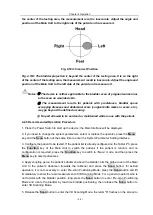
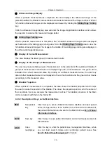
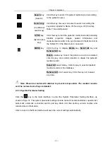
Fig. 4.15 Pre-scan Positioning Mode
The vertical line on the screen is the center line, and the area surrounded by the oblique lines on
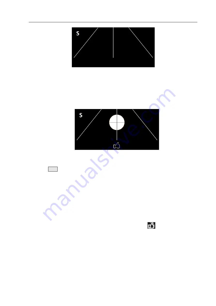
both sides of the center line represents the scanning area; the circle on the screen represents the
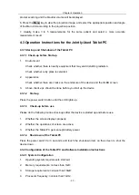
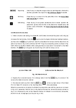
bladder, the center of the circle is the center of the bladder, as shown in Fig. 4.16 Bladder
Positioning Image.
Fig. 4.16 Bladder Positioning Image
Press the
Scan
button and hold, start pre-scanning and observe the screen:
①
When the bladder is not found in the scanning area, the circular graph and the indicated area
are not displayed as shown in Fig. 4.15. The scanning angle and position should be adjusted at
this moment until the bladder is found, that is, the circular graph appears on the screen.
②
When the bladder is found in the scanning area, it is displayed as a circular graph. The center
of the circle is the center of the bladder and the size of the circular area represents the size of the
estimated measured value in real time. The closer the center of the circle is to the center line, the
larger the size of the circular area is, and the more accurate the measurement will be.
The area below the screen is the indicated area, when the icon of "
" displays, it means the
center of the bladder is close to the center line, so the current scanning position is accurate, as
shown in Fig. 4.16.
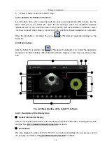
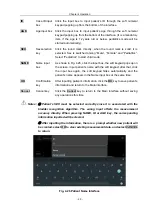
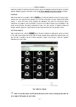
When the scanning position is not accurate, there will be appropriate prompt on the screen with
the arrow of left "
←
" or right "
→
" that directs you to move the Main Unit to the left or right according
to the direction of the arrow, as shown in Fig. 4.17a and Fig. 4.17b.


