MD8000
Rev. H
MD8000 Installation Procedures
3-6.3
Required Pre-Installation Requirements
Prior to installation of a chassis in a rack or cabinet, the following procedure
must
me
accomplished.
1. Locate the socket-outlet from which the equipment is to be powered.
2. Check that the socket-outlet provides a connection to the building protective earth.
a. If it does, the chassis can be connected to this outlet. Proceed to the "MD8000
Chassis Installation Procedures” shown below.
b. If it
does not
, proceed to Step 3.
DO NOT
connect chassis power at this time.
3. Arrange for the installation of a PROTECTIVE EARTHING CONDUCTOR from the
separate protective earthing terminal to the protective earth wire in the building.
4. When completed, proceed to "MD8000 Chassis Installation Procedures” shown below.
MD8000 Chassis Installation Procedures
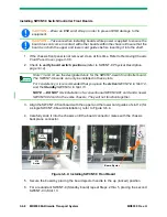
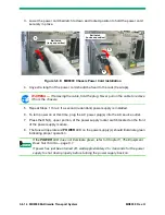
The procedures contained in this section are placed in a logical sequence for installation of a
new chassis in a 19-inch rack or cabinet.
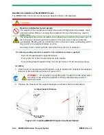
It is important that the following Warning Notes are read prior to installation.
This equipment generates, uses, and can radiate radio frequency energy which may
cause interference to radio communications.
Operation of this equipment in a residential area may cause interference to TV and
radio reception, in which case the user, at his own expense, must take whatever
measures may be required to correct the interference.
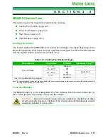
Fans are located on the front and rear of the chassis. Do not block the air circulation
vents or fans as this will cause overheating of the equipment, which may result in an
equipment failure or a fire.
CAUTION —
If any procedure is used as a “standalone” procedure, it is required that
you read the Warning and Caution Notes at the beginning of this section.
WARNING —
Read all Warning and Caution Notes found at the beginning of this
Chapter.
WARNING —
Prior to installation of a chassis in a rack or cabinet, the Pre-Installation
Requirements procedure
must
me accomplished. Refer to Required Pre-Installation
Summary of Contents for MD8000 Series
Page 1: ...MD8000 Multimedia Transport System Operational Manual For Release 8 21 MD8000 Rev H ...
Page 2: ......
Page 3: ...MD8000 Multimedia Transport System Operational Manual For Release 8 21 MD8000 Rev H ...
Page 6: ......
Page 12: ...vi MD8000 Transport System MD8000 Rev H This Page Intentionally Left Blank ...
Page 20: ...1 8 MD8000 Multimedia Transport System MD8000 Rev H This Page Intentionally Left Blank ...
Page 56: ...2 36 MD8000 Multimedia Transport System MD8000 Rev H Figure 2 32 SWCNT 2 State Transition ...
Page 60: ...3 2 MD8000 Multimedia Transport System MD8000 Rev H This Page Intentionally Left Blank ...
Page 66: ...3 1 6 MD8000 Multimedia Transport System MD8000 Rev H This Page Intentionally Left Blank ...
Page 70: ...3 2 4 MD8000 Multimedia Transport System MD8000 Rev H This Page Intentionally Left Blank ...
Page 78: ...3 3 8 MD8000 Multimedia Transport System MD8000 Rev H This Page Intentionally Left Blank ...
Page 84: ...3 5 4 MD8000 Multimedia Transport System MD8000 Rev H This Page Intentionally Left Blank ...


