3-6.10 MD8000 Multimedia Transport System
MD8000 Rev. H
Installing Trunk or Channel Service Front Boards
1. If the chassis front panel is not removed, do so at this time. Refer to
.
2. Check
MD8000 Series Trunk and Channel Service Operational Manual (MD8000)
to
verify board switch positions
, SFP installation, and front panel LED/Component
settings and descriptions:
3. If the board has optical I/O interfaces, it is recommended to clean the optical connector
of the board prior to installation. Refer to
Appendix A, Cleaning Fiber Optic connectors
for detailed cleaning procedures.
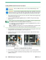
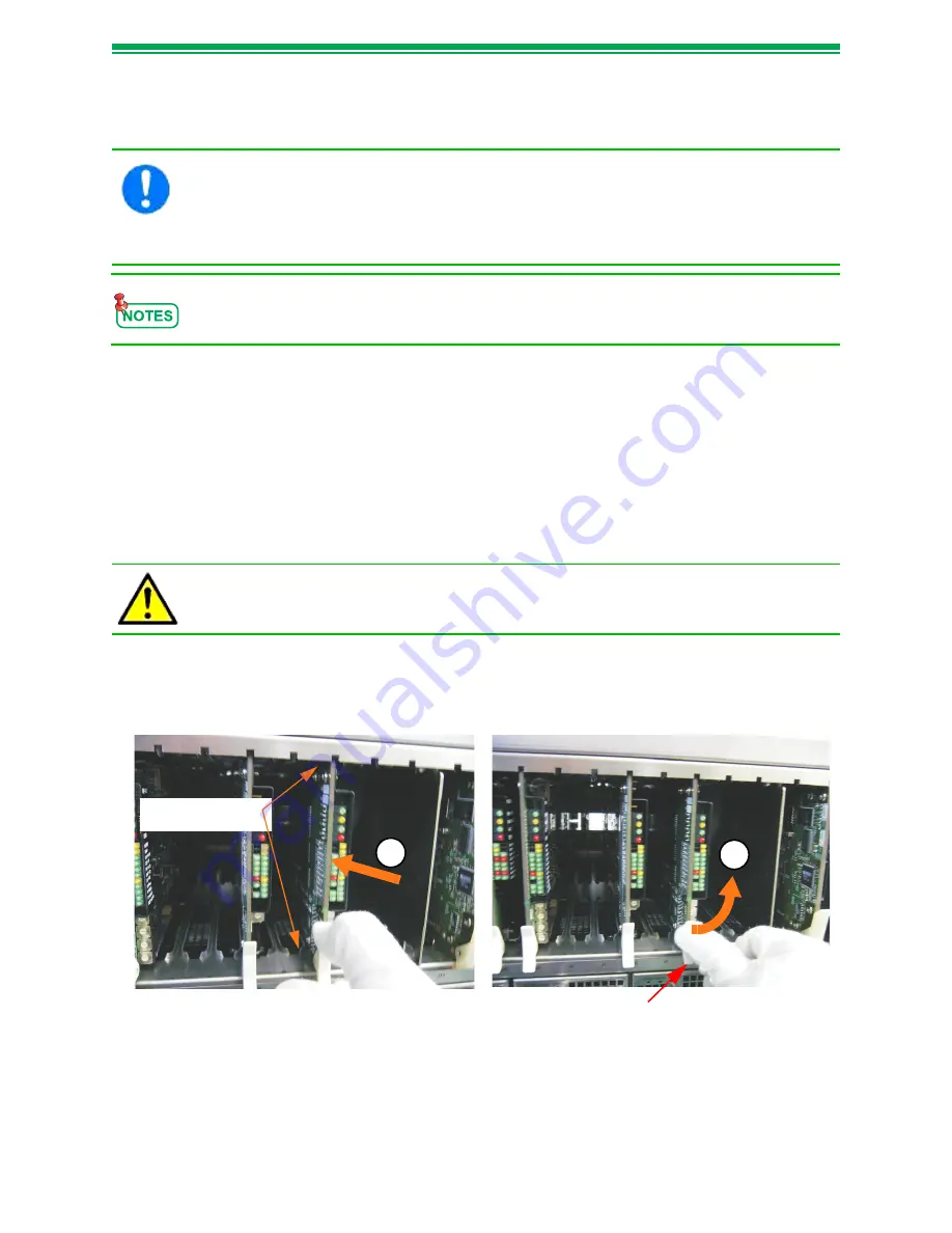
4. Align the board with the upper and the lower card guides, and carefully slide it into the
chassis (making sure it does not contact adjacent units) until board connector mates
with the chassis backplane connector (Figure 3-6.5).
Figure 3-6.5: Installing User Interface Front Boards
5. Secure the board by placing the board ejector handle to the up (locked) position.
CAUTION —
Wear an ESD wrist strap in order to prevent ESD damage to the
equipment.
CAUTION —
Take care when installing boards while the power is applied to ensure
the board does not come in contact with other boards within the chassis. Ensure that
the board is in both the upper and lower card guides before inserting it into the shelf.
This procedure covers the physical installation of the rear boards into the MD8000
Chassis. Refer to MD8000 Series Trunk and Channel Service Operational Manual
(MD8000) for functionality and any special module installation instructions.
CAUTION —
When installing a front board, make sure that you align the board with
both the upper and the lower card guides. Failing to do so may cause a board
malfunction, a fire or electrical shock while 'Hot Swapping' the board.
4
5
Upper and Lower
Card Guides
Board Ejector
Summary of Contents for MD8000 Series
Page 1: ...MD8000 Multimedia Transport System Operational Manual For Release 8 21 MD8000 Rev H ...
Page 2: ......
Page 3: ...MD8000 Multimedia Transport System Operational Manual For Release 8 21 MD8000 Rev H ...
Page 6: ......
Page 12: ...vi MD8000 Transport System MD8000 Rev H This Page Intentionally Left Blank ...
Page 20: ...1 8 MD8000 Multimedia Transport System MD8000 Rev H This Page Intentionally Left Blank ...
Page 56: ...2 36 MD8000 Multimedia Transport System MD8000 Rev H Figure 2 32 SWCNT 2 State Transition ...
Page 60: ...3 2 MD8000 Multimedia Transport System MD8000 Rev H This Page Intentionally Left Blank ...
Page 66: ...3 1 6 MD8000 Multimedia Transport System MD8000 Rev H This Page Intentionally Left Blank ...
Page 70: ...3 2 4 MD8000 Multimedia Transport System MD8000 Rev H This Page Intentionally Left Blank ...
Page 78: ...3 3 8 MD8000 Multimedia Transport System MD8000 Rev H This Page Intentionally Left Blank ...
Page 84: ...3 5 4 MD8000 Multimedia Transport System MD8000 Rev H This Page Intentionally Left Blank ...

