background image

IMPORTANT:

Prevent wear on the webbing 

by keeping the Retractor and 

webbing aligned with the Frame 

Top Tube and Keeper.

WARNING!

Please ensure there is adequate 

clearance between your legs and 

the LapStacker

®

 components. If 

not, you may develop a pressure 

injury from rubbing against these 

components. 

Items Required:


Wheel Chair


3.0mm Allen Key


2 x Clamp, Bracket and 

Retractor Assemblies

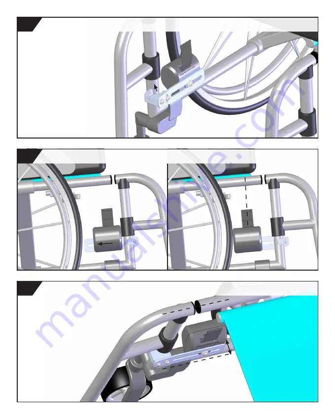
Adjust Retractor position so that webbing aligns with ideal Keeper position. 

Adjust Clamp angle to align Bracket with the Frame Top Tube. 

Attach the Clamp and assembled parts to the Front Vertical Frame Tube.

5.

6.

7.

29

Summary of Contents for LapStacker

Page 1: ...Installation Guide ...

Page 2: ...acker improves freedom and independence in your life You can email me anytime at info lapstacker com or simply tag us on social media and use lapstacker Of course we d also like to hear about how we can improve so please feel free to let us know The LapStacker is made from quality materials to our exacting standards and should last many years of hard use I hope you ll love it as much as I do and l...

Page 3: ...ur Retractor to the mounting components and fix the completed assembly to your wheelchair STEP TWO Keeper Installation Use the contents to page find the Keeper install instructions for the correct Keeper style you have purchased Follow the Keeper install instructions to fit the Keepers to your chair STEP THREE Buckle Installation Follow the Buckle installation guide to fit the buckles to the webbi...

Page 4: ...nce Vision Installation Care of your LapStacker Retractor Installation Frame Top Tube Cross Frame Rigidizer Bar Batec Style Attachment Lower Horizontal Frame Tube Front Vertical Frame Tube Kuschall K Series Keeper Installation Long Keeper Short Keeper Snap Fit Universal Direct Mount Side Guard Keeper Buckle Installation Final Adjustment Thread Protector Installation 3 ...

Page 5: ...Contents Page continued Page 58 65 Contents Power Chair Installation Trouble Shooting 4 ...

Page 6: ...apStacker is designed as an aid only You will still need to carefully place items on your lap and monitor them while using the LapStacker Items can move even with the LapStacker securing them and we take no responsibility for any damage to goods or people should items fall while you are using the LapStacker We do not recommend using the LapStacker for extensive periods of time to hold items on you...

Page 7: ...ey are reinstalled and secured correctly Failure to do so may result in their failure and injury to you or others If you are installing the LapStacker on a carbon fibre chair please be aware that over tensioning the Clamps or Keepers may crack or damage your chair Tighten slowly and with caution Do not over tighten Warnings Buckle Installation To prevent your Buckles coming off of the webbing plea...

Page 8: ...e Brackets are made of aluminium to reduce weight and are not designed to be pulled on or adjusted without first loosening the Clamp fasteners Please be gentle with them or they may break Wipe components clean with a damp cloth and avoid the use of chemical detergents which may damage the plastic surfaces The straps may be cleaned using water and a damp cloth We suggest removing the retractors ful...

Page 9: ...Frame Top Tube Installation For Keeper Installation please see page 35 For Buckle Installation please see page 50 For Final Adjustment please see page 55 For Trouble Shooting please see page 65 8 ...

Page 10: ...ease see the Keeper install section beginning page 35 Clamp A 2 x Clamp B 2 x M5 x 10mm Screw 4 x M5 Washer 6 x M5 x 12mm Screw 2 x M4 Washer 2 x M5 x 16mm Screw 2 x 3 0mm Allen Key 1 x M4 x 8mm screw 2 x 2 5mm Allen Key 1 x Retractor Unit 2 x 90 Bracket Left Side 1 x 90 Bracket Right Side 1 x 9 ...

Page 11: ...acker to secure an item Find the midpoint for this object and take a note of this position on the Frame Top Tube of your wheelchair The Keeper MUST align with the centre of the webbing from the retractor unit Ensure your ideal Keeper location allows room for the Retractor Unit Clamps and Brackets Determine Approximate Keeper Location 1 RETRACTOR CLAMP WEBBING BRACKET IDEAL KEEPER POSITION CENTRE O...

Page 12: ...d 1 x 90 Bracket LEFT 1 x 90 Bracket RIGHT 4 x M5 10mm Screws 4 x M5 washers 3 0mm Allen Key Items Required 2 x Retractor Units 2 x M5 12mm Screws 2 x M5 washers 3 0mm Allen Key Fasten Brackets to the Clamps Fasten Retractors to the Brackets loosely Fasten Clamps together loosely 2 3 4 11 ...

Page 13: ...RNING Please ensure there is adequate clearance between your legs and the LapStacker components If not you may develop a pressure injury from rubbing against these components Items Required 3 0mm Allen Key 2 x Clamp Bracket and Retractor Assemblies Adjust Retractor position so that webbing aligns with ideal Keeper position Check underseat clearance seated Adjust Clamp angle if necessary Attach the...

Page 14: ...Cross Frame Rigidizer Bar Installation Above The Cross Frame Rigidizer Bar For further information please see page 16 Below The Cross Frame Rigidizer Bar For further information please see page 17 13 ...

Page 15: ...Keeper components please see the Keeper install section beginning page 35 Clamp A 2 x Clamp B 2 x M5 x 10mm Screw 4 x M5 Washer 6 x M5 x 12mm Screw 2 x M4 Washer 2 x M5 x 16mm Screw 2 x 3 0mm Allen Key 1 x M4 x 8mm screw 2 x 2 5mm Allen Key 1 x Retractor Unit 2 x Cross Bar Bracket 2 x 14 ...

Page 16: ...er to secure an item Find the midpoint for this object and take a note of this position on the Frame Top Tube of your wheelchair The Keeper MUST align with the centre of the webbing from the Retractor Unit Ensure your ideal Keeper location allows room for the Retractor Unit Clamps and Brackets Determine Approximate Keeper Location 1 RETRACTOR CLAMP WEBBING KEEPER BRACKET IDEAL KEEPER POSITION CENT...

Page 17: ...and the seat base you may need to mount the Retractor on the underside of the Cross Frame Rigidizer Bar See Step 6 for more details Items Required 2 x Clamp A 2 x Clamp B 2 x M5 16mm Screws 3 0mm Allen Key Items Required 2 x Cross Bar Bracket 4 x M5 10mm Screws 4 x M5 washers 3 0mm Allen Key Items Required 2 x Retractor Units 2 x M5 12mm Screws 2 x M5 washers 3 0mm Allen Key Fasten Brackets to the...

Page 18: ...o the Frame Top Tube but clear of any brake mechanism components Attach the Clamp and assembled parts to the Cross Frame Rigidizer Bar 5 7 WARNING It is important that you allow enough clearance between the Retractor and the seat base so that when you are seated there is no downwards pressure on the Retractor Unit Failure to do so will stress the Bracket and may cause it to fail over time If there...

Page 19: ...position so that webbing aligns with ideal Keeper position Repeat the process with components mirrored for the opposite side 9 10 Adjust Clamp angle so that the Cross Bar Bracket is parallel with the Frame Top Tube 8 18 ...

Page 20: ...Lower Horizontal Frame Tube Installation External Mounting Option See Step 6 for more information Internal Mounting Option See Step 6 for more information 19 ...

Page 21: ...nts please see the Keeper install section beginning page 35 Clamp A 2 x Clamp B 2 x M5 x 10mm Screw 4 x M5 Washer 6 x M5 x 12mm Screw 2 x M4 Washer 2 x M5 x 16mm Screw 2 x 3 0mm Allen Key 1 x M4 x 8mm screw 2 x 2 5mm Allen Key 1 x Retractor Unit 2 x 90 Bracket Left Side 1 x 90 Bracket Right Side 1 x 20 ...

Page 22: ...er to secure an item Find the midpoint for this object and take a note of this position on the Frame Top Tube of your wheelchair The Keeper MUST align with the centre of the webbing from the Retractor Unit Ensure your ideal Keeper location allows room for the Retractor Unit Clamps and Brackets Determine Approximate Keeper Location 1 RETRACTOR BRACKET WEBBING KEEPER CLAMP IDEAL KEEPER POSITION CENT...

Page 23: ...d 1 x 90 Bracket LEFT 1 x 90 Bracket RIGHT 4 x M5 10mm Screws 4 x M5 washers 3 0mm Allen Key Items Required 2 x Retractor Units 2 x M5 12mm Screws 2 x M5 washers 3 0mm Allen Key Fasten Brackets to the Clamps Fasten Retractors to the Brackets loosely Fasten Clamps together loosely 2 3 4 22 ...

Page 24: ...s Items Required Wheel Chair 3 0mm Allen Key 2 x Clamp Bracket and Retractor Assemblies You can shift the position of the Retractor inwards towards your legs by swapping the Clamp and assembled parts to the opposite side Attach the Clamp and assembled parts to the Lower Horizontal Frame Tube 5 6 Adjust Retractor position so that webbing aligns with ideal Keeper position 7 23 ...

Page 25: ...nt Vertical Frame Tube Installation For Keeper Installation please see page 35 For Buckle Installation please see page 50 For Final Adjustment please see page 55 For Trouble Shooting please see page 65 24 ...

Page 26: ...r Keeper components please see the Keeper install section beginning page 35 Clamp A 2 x Clamp B 2 x M5 x 10mm Screw 4 x M5 Washer 6 x M5 x 12mm Screw 2 x M4 Washer 2 x M5 x 16mm Screw 2 x 3 0mm Allen Key 1 x M4 x 8mm screw 2 x 2 5mm Allen Key 1 x Retractor Unit 2 x Flat Brackets 2 x 25 ...

Page 27: ...er to secure an item Find the midpoint for this object and take a note of this position on the Frame Top Tube of your wheelchair The Keeper MUST align with the centre of the webbing from the Retractor Unit Ensure your ideal Keeper location allows room for the Retractor Unit Clamps and Brackets Determine Approximate Keeper Location 1 RETRACTOR CLAMP WEBBING KEEPER BRACKET IDEAL KEEPER POSITION CENT...

Page 28: ...ws 3 0mm Allen Key Items Required 2 x Flat Bracket 4 x M5 10mm Screws 4 x M5 washers 3 0mm Allen Key Fasten Brackets to the Clamps OPTION A Fasten Clamps together loosely 2 3a OPTION A allows the Retractor to be placed close up to the Front Vertical Tube 27 ...

Page 29: ...ers 3 0mm Allen Key Items Required 2 x Retractor Units 2 x M5 12mm Screws 2 x M5 washers 3 0mm Allen Key Fasten Retractors to the Brackets loosely Fasten Clamps together loosely OPTION B 3b 4 OPTION B increases adjustment distance from Front Vertical Frame Tube 28 ...

Page 30: ...Stacker components If not you may develop a pressure injury from rubbing against these components Items Required Wheel Chair 3 0mm Allen Key 2 x Clamp Bracket and Retractor Assemblies Adjust Retractor position so that webbing aligns with ideal Keeper position Adjust Clamp angle to align Bracket with the Frame Top Tube Attach the Clamp and assembled parts to the Front Vertical Frame Tube 5 6 7 29 ...

Page 31: ...Kuschall K Series Installation For Keeper Installation please see page 35 For Buckle Installation please see page 50 For Final Adjustment please see page 55 For Trouble Shooting please see page 65 30 ...

Page 32: ...lease see the Keeper install section beginning page 35 Clamp A 2 x Clamp B 2 x M5 x 10mm Screw 4 x M5 Washer 6 x M5 x 12mm Screw 2 x M4 Washer 2 x M5 x 16mm Screw 2 x 3 0mm Allen Key 1 x M4 x 8mm screw 2 x 2 5mm Allen Key 1 x Retractor Unit 2 x 90 Bracket Left Side 1 x 90 Bracket Right Side 1 x 31 ...

Page 33: ...er to secure an item Find the midpoint for this object and take a note of this position on the Frame Top Tube of your wheelchair The Keeper MUST align with the centre of the webbing from the Retractor Unit Ensure your ideal Keeper location allows room for the Retractor Unit Clamps and Brackets Determine Approximate Keeper Location 1 RETRACTOR CLAMP WEBBING KEEPER BRACKET IDEAL KEEPER POSITION CENT...

Page 34: ...d 1 x 90 Bracket LEFT 1 x 90 Bracket RIGHT 4 x M5 10mm Screws 4 x M5 washers 3 0mm Allen Key Items Required 2 x Retractor Units 2 x M5 12mm Screws 2 x M5 washers 3 0mm Allen Key Fasten Brackets to the Clamps Fasten Retractors to the Brackets loosely Fasten Clamps together loosely 2 3 4 33 ...

Page 35: ...y from rubbing against these components Items Required 3 0mm Allen Key 2 x Clamp Bracket and Retractor Assemblies Rotate the 90 Bracket so that the Retractor is parallel with the seat base Adjust Retractor position so that webbing aligns with ideal Keeper position Attach the Clamp and assembled parts to the angled Frame Top Tube 5 6 7 34 ...

Page 36: ...your side and imagine using the LapStacker to secure an item Find the midpoint for this object and take a note of this position on the Frame Top Tube of your wheelchair The Keeper MUST align with the centre of the webbing from the Retractor Unit Ensure your ideal Keeper location allows room for the Retractor Unit Clamps and Brackets RETRACTOR CLAMP WEBBING BRACKET IDEAL KEEPER POSITION CENTRE OF W...

Page 37: ... 2 x Hook Loop Velcro 2 x Items Required 1 x Long Keeper Items Required 1 x Pencil Position the Long Keeper so that it aligns with the Retractor strap and is clear of any wheel guards Mark out the position of the Long Keeper on your seat base using a pencil 1 2 36 ...

Page 38: ...of the Long Keeper so that both locations have as much velcro coverage as possible Attach the Long Keepers to the seat base Ensure the area is clean and dry and free from grease 3 4 5 It is important to locate the Keeper so that it is as close to the edge of your cushion but not sticking out so far that it is in the way off your hands while pushing 37 ...

Page 39: ...Components The items highlighted below are required from the main fastener set Snap Fit Fastener Set M5 x 10mm Screw 4 x M5 Washer 6 x M5 x 12mm Screw 2 x M4 Washer 2 x M5 x 16mm Screw 2 x 3 0mm Allen Key 1 x M4 x 8mm screw 2 x Short Keeper 2 x Snap Fit Base 2 x 38 ...

Page 40: ...Snap Fit Base Items Required 1 x 2 5mm Allen Key Attach the Short Keeper to the Snap Fit Base using the M4 washers and fasteners Adjust the Short Keeper so that it aligns with the webbing Tighten in place Press the Snap Fit Base onto the Frame Top Tube so that it aligns with the Retractor webbing 1 2 3 39 ...

Page 41: ...ms highlighted below are required from the main fastener set Universal Base Rubber Pad Fastener Set M5 x 10mm Screw 4 x M5 Washer 6 x M5 x 12mm Screw 2 x M4 Washer 2 x M5 x 16mm Screw 2 x 3 0mm Allen Key 1 x M4 x 8mm screw 2 x Short Keeper 2 x Cable Ties 4 x Universal Base 2 x Rubber Pad 2 x 40 ...

Page 42: ...st the position of the Universal Base to ensure it aligns with the Retractor webbing Tighten cable ties firmly in place Using a set of pliers can make this easier Attach the Universal Base to the Frame Top Tube using two cable ties Do not fully tighten the cable ties yet 1 2 3 41 ...

Page 43: ...ems Required 1 x 2 5mm Allen Key Attach the Short Keeper to the Universal Base using the M4 washers and fasteners Adjust the Short Keeper so that it aligns with the webbing Tighten in place Adjust cable tie ends so that they are kept clear of your seat legs and the webbing Trim the ends flush and AVOID LEAVING SHARP EDGES 4 5 6 42 ...

Page 44: ...ems highlighted below are required from the main fastener set Universal Base Rubber Pad Fastener Set M5 x 10mm Screw 4 x M5 Washer 6 x M5 x 12mm Screw 2 x M4 Washer 2 x M5 x 16mm Screw 2 x 3 0mm Allen Key 1 x M4 x 8mm screw 2 x Short Keeper 2 x Cable Ties 4 x Universal Base 2 x Rubber Pad 2 x 43 ...

Page 45: ...er Feed the cable tie through the Buckle recess of the Short Keeper and back up through the small slot Connect the cable ties around the Frame Top Tube Do not tighten the cable ties fully yet Wrap Rubber Pad around the Frame Top Tube Hold the Short Keeper against the Rubber Pad and Frame Top Tube 2 3 1 44 ...

Page 46: ...le ties so that the Short Keeper is held firmly in position Using a pair of pliers to grip the cable ties will make this job easier Adjust cable tie position so that the end is not exposed when in use Finally trim each cable tie flush AVOID LEAVING SHARP EDGES Adjust the Short Keeper so that it aligns with the webbing 5 6 4 45 ...

Page 47: ...ded if you choose to use this method of fixing Please consult with your wheelchair provider for advice prior to making any alterations to your chair Adaptdefy will not be held liable for any voided warranties or damage should you choose to use this method Fasteners are not included Webbing Loop Extension Side Guard Keeper 2 x OPTION Attaching Side Guard Keeper using fasteners Fasteners are not pro...

Page 48: ...the Side Guard Keeper 3 Items Required 2 x Side Guard Keepers Hold the Side Guard Keeper against the inside face of your side guard aligned with the Retractor webbing and level with the top of your cushion 2 Seat Cushion Webbing Items Required Cleaning product if necessary Start by cleaning each side guard removing any oil dirt or dust build up 1 47 ...

Page 49: ...de Guard Keepers Press the Side Guard Keeper and adhesive firmly against the side guard 4 When should I use Webbing Loop Extensions If the existing webbing loop is hidden between the wheelchair side guard and your thigh when seated If you are having difficulty accessing and using the existing webbing loop Items Required 2 x Webbing Loop Extensions 48 ...

Page 50: ...bing Loop Extension through the existing webbing loop 6 Fasten the plastic clips together by pushing the locking tab into the reciever 7 Rotate the Webbing Extension Loop so that the plastic clips are concealed 8 49 ...

Page 51: ...kles Components Before you begin The Buckles work best with Buckle B being matched with your dominant hand Take note of which side of the chair this will be when seated Buckle A 1 x Dominant Hand Side Buckle B Buckle B 1 x Buckle A 50 ...

Page 52: ...RNING If you thread the Buckles onto this large loop they will eventually fall off 2 Centre Loop Default The centre loop is the default Buckle install location This location is easy to install and will hold the Buckle comfortably in place whilst allowing the Buckles to rotate freely 3 Small Loop The small loop will hold the Buckles in place firmly If you are needing the Buckles to be held more sec...

Page 53: ... be fitted with the steel plate facing upwards and the fabric loop above the Buckle Thread the sewn webbing loop through the Keeper Buckle A Carefully remove the golf tee from the webbing Do not let the webbing go as it can retract inside the housing 3 2 1 52 ...

Page 54: ...uld be fitted with the logo facing upwards and the fabric loop above the Buckle Thread the sewn webbing loop through the Keeper Buckle B Carefully remove the golf tee from the webbing Do not let the webbing go as it can retract inside the housing 6 5 4 53 ...

Page 55: ...en assembled the Buckles should lock together with the webbing loops sitting above the Buckles The Buckles should sit directly against the object you are carrying 7 Dominant Hand Side Buckle B Buckle A 54 ...

Page 56: ...Final Adjustment Adjust the alignment of the Retractor so that the webbing runs smoothly through the Keeper Finally check all fasteners are done up tight Your LapStacker is now ready to use 55 ...

Page 57: ...To make install easier secure the webbing so that it cannot retract back towards the housing Thread Protector Install Video IMPORTANT The Thread Protector is designed to cover the stitching when the Magnetic Buckles are fitted into the centre loop 2 If using the small loop 3 the top row of stitching will remain exposed LapStacker Installed 3 2 1 Small Loop Centre Loop Large Loop NOT FOR BUCKLE INS...

Page 58: ...ntre Thread Protector with the webbing Ensure the partition in the Thread Protector fits either side of the Magnetic Buckle With the Thread Protector positioned correctly press down firmly on the webbing to create a strong bond Items Required 2 x Thread Protector 2 x LapStacker Installed Fold both tabs from the right side around the the webbing Fold remaining two tabs over to complete the installa...

Page 59: ... set is suitable for all Permobil power chairs If you own a different brand of power chair you will need to contact Adaptdefy to work out if this will fit your chair prior to purchasing For Buckle Installation please see page 50 For Trouble Shooting please see page 65 58 ...

Page 60: ...ener Set Retractor Units Brackets 4 0mm Allen Key Side Guard Keeper 2 x M6 x 12mm Screw 2 x M5 Washer 6 x M6 Slot Nut 2 x 1 x M5 x 12mm Screw 2 x 3 0mm Allen Key 1 x M3 x 6mm screw 2 x 2 0mm Allen Key 1 x Retractor Unit 2 x Compact 1 Bracket 2 x 59 ...

Page 61: ...hile in your power wheelchair look down at your side and imagine using the LapStacker to secure an item Find the midpoint for this object and take a note of this position on the extrusion at the side of your seat Determine Approximate Keeper Location 1 BRACKET EXTRUSION WEBBING KEEPER RETRACTOR IDEAL KEEPER POSITION CENTRE OF WEBBING 60 ...

Page 62: ...he side as these will be reinserted once the LapStacker has been installed Items Required 2 x Retractor 2 x Compact 1 Bracket 2 x M5 washers 2 x M5 12mm Screws 3 0mm Allen Key Items Required 2 x Bracket Assembly 2 x M6 12mm Screws 2 x M6 Slot Nut 4 0mm Allen Key Fasten M6 Slot Nut to the Bracket loosely Remove seat extrusion end cap Fasten Retractor to the Bracket 2 3 4 61 ...

Page 63: ... if it does not slide in easily Tighten the assembly to the extrusion Slide Bracket Assembly onto the seat extrusion 5 7 WARNING Avoid over tightening the fasteners as this will strip the thread Align centre of the webbing with the ideal Keeper position 6 Items Required 2 x Bracket Assembly 4 0mm Allen Key 62 ...

Page 64: ...ed webbing through Keeper 8 10 WARNING Avoid over tightening the fasteners as this will strip the thread Install Magnetic Buckles A and B See page 50 for detailed instructions 9 Items Required 2 x M3 8mm Screws 2 0mm Allen Key 63 ...

Page 65: ...Assembly is now completed Enjoy using your LapStacker Reinsert extrusion end cap 11 Repeat install process for the opposite side 12 64 ...

Page 66: ...etractor Unit Assembly and Main Components Please reference this illustration when using the trouble shooting guide on the following page TOP HOUSING LOCKING TAB WEBBING SPOOL BASE HOUSING RETRACTOR WEBBING FASTENERS 65 ...

Page 67: ... webbing until the folded section is revealed and the fold is removed VI Release the Locking Tab VII Carefully let the webbing retract back onto the spool Make sure the webbing remains flat and level with the Retractor Unit to avoid it folding back onto itself VIII Fasten the Top Housing back in place and reinstall on your chair 2 Webbing retracts completely inside the Retractor Housing I Remove t...

Page 68: ...ming off please view section 2 of the trouble shooting guide page 66 II With the webbing outside of the housing feed the webbing loop back through the Keeper slot III Attach the Buckle using the central loop 2 OR the smallest loop 3 adjacent to the end of the sewn section see figure below DO NOT use the large finger loop IV For full instructions on Buckle installation please see page 50 67 ...

Reviews: