© MEDISTIM 2015
6
6
3. TECHNICAL DESCRIPTION
The VeriQ™ system is designed for intra-operative quality
control and the need for documentation of surgical proce-
dures. Through its capability to measure transit time volume
flow and Doppler flow velocity, the VeriQ™ can help develop
optimal grafting strategies and to document graft patency.
The VeriQ™ system consists of a 19 inch touch screen, dis-
playing significant flow variables. The menu-driven program
is managed through the use an intuitive graphical, icon-driven
interface. Improper data entry and incorrect operations are
minimized through the use of an on-screen keyboard that
appears only when it is required.
The VeriQ™ uses five main screen views; the Home screen,
the Measure screen, the Data screen, the Help screen and
the System Settings screen. The user can move between
screens by pressing the screen tabs located in the top left
corner.
All reports and documentation can be written directly to the
printer connected to the system.
3.1
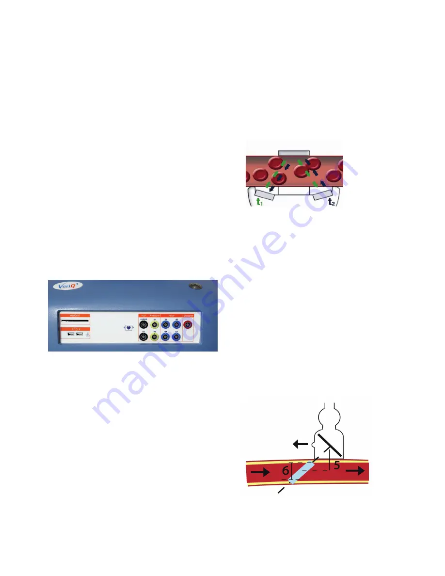
Front panel and channel configurations
The VeriQ™ system can be supplied with a range of differ-
ent channel configurations to accommodate various clinical
needs. The channel configurations are described in the model
number, where the first digit lists the number of flow chan
-
nels, the second digit is the Doppler channel, third digit is
the number of pressure channels, and the fourth digit is the
number of auxiliary channels.
The VeriQ™ 4122 has four flow channels, one Doppler chan
-
nel two pressure channels and two auxiliary channels. The
model number is part of the system identity and can be found
on the front of the system under the blue top cover
.
3.1.1
Pay-Per-Procedure
The VeriQ™ system is either supplied as a capital purchase,
or through a pay-per-procedure (PPP) program, where license
“smart cards” are required in order to activate the device.
3.1.2
USB port connections
The VeriQ™ system has 2 USB 2.0 ports located on the left
side of the front panel for connecting external equipment like
a memory stick to import or export data .
Warning
The front panel USB connector has no galvanic separation.
In order to maintain continued patient safety, no equipment
powered by an external power source must be connected to
the USB port during clinical use of the system.
3.2 Principle of measurements
Transit time flow volume
Medistim transit time probes surround the vessel, gener-
ating a uniform ultrasound field across the vessel lumen.
Ultrasound pulses are transmitted from a crystal on one side
of the probe, to the reflector, and back to a crystal on the
opposite side. The transit time is measured for each pulse,
with the difference in transit time between the pulses going
upstream and downstream being proportional to the volume
(Q) passing through the probe.
Doppler principle
When an ultrasound beam is reflected by a moving object,
the frequency of the reflected pulse is changed. An object
moving towards the ultrasound beam will compress the
waveform and increase the frequency. Correspondingly, an
object moving away from the beam will lengthen the wave-
form and decrease the frequency.
The change in frequency, also called Doppler shift, represents
the velocity and direction of the moving target. To limit prob-
lems relating to the ultrasound beam’s angle of incidence
with the blood, the Doppler probe has a built-in angle of
45 degrees. Holding the probe perpendicular to the vessel
direction will ensure accurate velocity measurements Note
that this causes the probe to measure the velocities in front
or behind the actual probe position, but never right under the
probe.
The VeriQ™ applies a pulsed Doppler, allowing the user to
control the depth from where the velocity should be mea-
sured. Additionally, sample volume is adjustable, and select-
ed as a range around the depth setting. The default settings
are a depth of 5 mm, and a volume of 6 mm. These settings
allow for sampling flow velocities at depths from to 2 to 8 mm
from the probe surface.


