Installation Manual
GB
12
Power supply
The electrical power unit consists of a reversable single phase
condensor motor with integrated electronic stop switch, brake and
transmission.
The lift can be controlled via:
1. radio remote control No. 5944-0
2. IR remote control No. 5699-13
3. key switch No. 5944-1
4. up/down switch No. 5944-2
5. media control system (e.g. Kindermann, AMX, etc.)
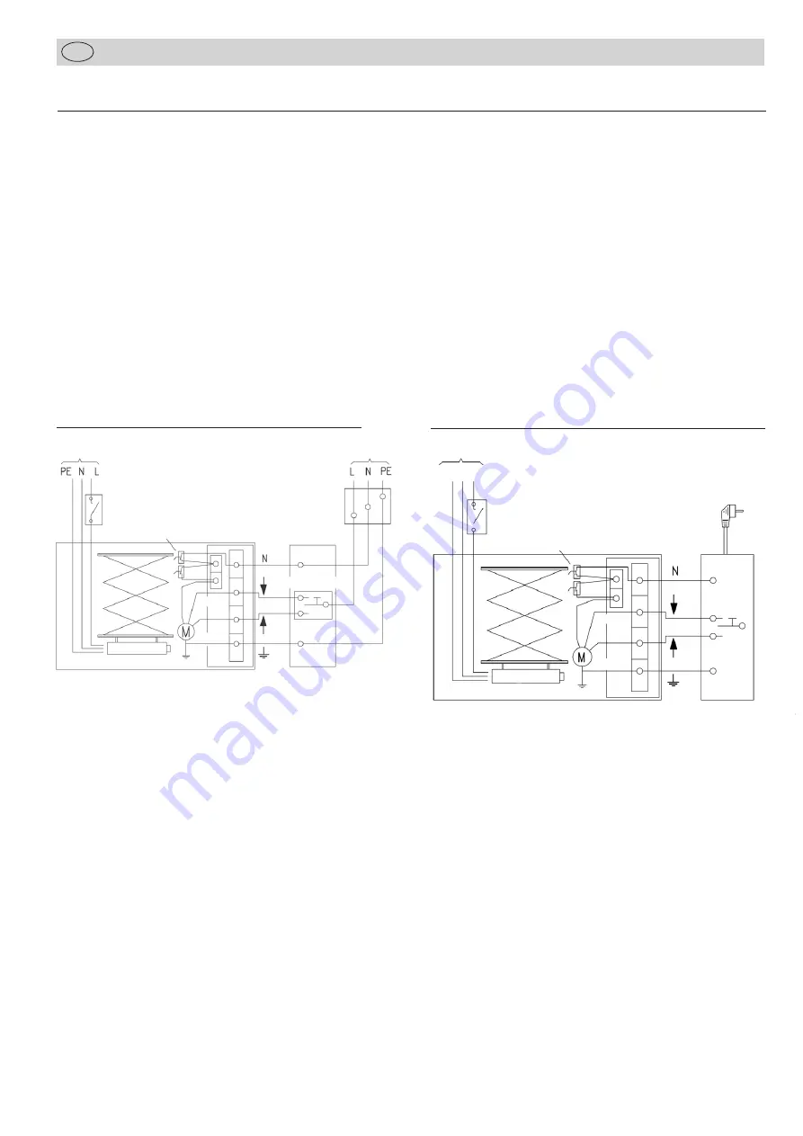
The connection with the power supply should be via the power
socket of the lift and an external socket with on/off switch.
All wiring goes through the appropriate opening in the upper
frame. The connection cable for the projector and the cables for
the safety switches have been pre-mounted on the right hand pairs
of the concertina elements. Use the cable guides on the left hand
pairs of the concertina elements for installating the signal and
control cables.
Fix the supplied flexible spiral and the cable clips, then the signal
and control cables in the same way as the pre-mounted cables.
Thus the cords cannot be squeezed or otherwise be damaged by
the concertina elements.
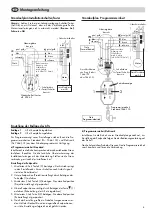
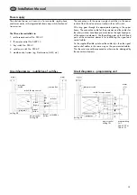
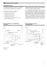
Circuit diagramme – installation of switches
mains
ceiling lift
projector
projector switch
switch for rope control
mains
power socket
ceiling lift
programming
unit
7466-100 or
7466-101
blue
black
brown
green/yellow
brown
green/yellow
PE N L
blue
black
Circuit diagramme – programming unit
mains
mains
projector
switch
switch for rop control
blue
black
brown
green/
yellow
ceiling lift
projector
power socket
ceiling lift
switch box
switches
junction box
blue
black
brown
green/
yellow
Summary of Contents for 22483
Page 22: ......

