background image

Installation Manual

GB

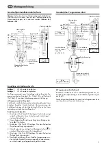
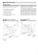
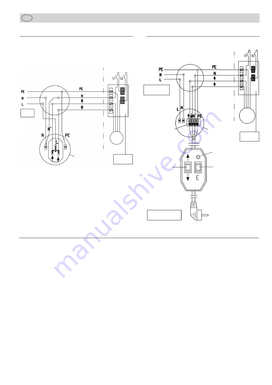
Wiring diagramme – programming unit

13

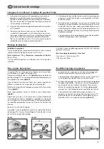
Stop position 1

Lift in complete upward position

Stop position 2

Lift in complete downward position

To programme new positions use the programming unit standard
(No. 7466-100) or electronic (No. 7466-101. See optional
accessories.

a) Programming unit standard

Install the unit according to the attached wiring diagramme. Make
sure that the colours of the installation cables are identical with
the colours of the motor cable. Connect with the mains only after
completing the installation!

Adjustment end positions:

1. Press button E (2) for at least 6 sec., the motor switches into

adjustment mode. Short stop after start indicates adjustment
mode!

2. Drive to the bottom end position (projection position).
3. Press button E (2) for at least 3 sec., bottom end position is set.
4. Drive to top end position (home position) carefully.
5. Press button E (2) for at least 3 sec., top end position (home

position) is set.

6. A trial run should be carried out upon completion of adjust-

ments. Adjustments are correct when the ceiling lift stops at
the set end positions.

Note:

Make sure that the cables to the on/off switches of the lift
are not exchanged! 

(brown = up, black = down)

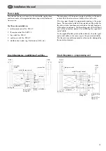
Wiring diagramme – installation of switches

   junction box
provided by the user

     mains

safety switch

green/yellow

blue

brown

    black

black

blue

green/yellow

blue

   box for switches
provided by the user

Up/down switch
e.g. 5944-2

Cable between
junction box and
box for switches
min. 6 wires
(e.g. NYM 7x1.5mm

2

)

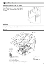
Adjusting the stop position of the lift

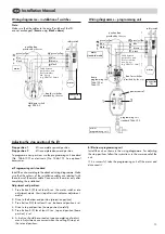
b) Electronic programming unit

Install the unit as shown in the wiring diagramme. For adjusting
the stop positions follow the instructions in the user manual of the
unit.

If it is successful, take the programming unit off the mains and
disconnect it.

  box for switches
provided by the user

safety switch

black

blue

   junction box
provided by the user

     mains
standard mode

clamp
programming unit
7466-100 or
7466-101

green/yellow

     motor

     motor

   connection
         lift

green/yellow

blue

brown

    black

programming unit
standard 7466-100

mains
programming unit

   connection
         lift

power control

2

1

black

brown

gr/ye

blue

Cable between
junction box and
box for switches
min. 6 wires
(e.g. NYM 7x1.5mm

2

)

Summary of Contents for 22483

Page 1: ...ME D I U MG mb H Wi l l s t t t e r s t r 7 4 0 5 4 9D s s e l d o r f 2 2 4 8 3 2 2 4 8 3 2 2 4 8 3 2 2 4 8 4 2 2 4 8 4 2 2 4 8 4...

Page 2: ...Projektor Halterung ausfahrbarer Hub Compact 80 bis 80 cm Compact 120 bis 120 cm Gewicht des Lifts Compact 80 24 kg Compact 120 26 kg max Projektorgr e 50 x 35 cm max Projektorgewicht 20 kg Stromverso...

Page 3: ...n 10 Vier Schraubens tze M3 M4 M5 M6 mit U Scheiben 11 Vier Verl ngerungsschienen mit Schrauben und Muttern zur erweiterten H heneinstellung der Deckenabschlussplatte 12 Optionale Deckenabschlussplatt...

Page 4: ...iltrommel auf Bitte kontrollieren Sie vor der ersten Inbetriebnahme dass das Seil in jedem Fall einlagig ohne berkreuzungen auf gewickelt ist Im Falle einer berkreuzung fahren Sie den Lift ganz heraus...

Page 5: ...rahmen vorgenommen Das Netzkabel f r den Projektor und die Kabel f r die Sicherheitsschalter sind bereits an den rechten Scherenpaaren vormontiert Verwenden sie die vorhandenen Kabelhalterungen an den...

Page 6: ...lt der Deckenlift an den eingestellten Endpositionen so ist die Einstellung erfolgreich durchgef hrt worden 6 Hinweis Achten Sie bei der Leitungsverlegung Schalter Taster Auf Ab zum Lift darauf dass...

Page 7: ...um ca 20 geneigt werden Stimmt die Ausrichtung des Projektors zur Leinwand kann die Schraube auf den Projektorhalter 8 mit einem Gabel schl ssel angezogen werden 2 Der Projektorhalter sitzt im Zentrum...

Page 8: ...t erreicht werden kann k nnen vier Verl ngerungs schienen 11 eingesetzt werden Abb Wartung und Pflege Der Deckenlift ist grunds tzlich wartungsfrei Einmal j hrlich sollte er auf Sicherheit und Zuverl...

Page 9: ...mm Projector mounting universal projector mount Lifting range Compact 80 up to 80 cm Compact 120 up to 120 cm Weight of the lift Compact 80 24 kg Compact 120 26 kg Max projector size 50 x 35 cm Max pr...

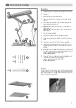
Page 10: ...ith distance bolts 10 four sets of screws M3 M4 M5 M6 with washers 11 four extension arms with screws and nuts for modified adjustment of the ceiling plate 12 optional ceiling plate with T profile for...

Page 11: ...lift on for the first time make sure that the rope lies one ply on the drum and does not intersect In case of an intersection lower the lift completely and let it move upwards cautiously A safety swit...

Page 12: ...n the right hand pairs of the concertina elements Use the cable guides on the left hand pairs of the concertina elements for installating the signal and control cables Fix the supplied flexible spiral...

Page 13: ...ust ments Adjustments are correct when the ceiling lift stops at the set end positions Note Make sure that the cables to the on off switches of the lift are not exchanged brown up black down Wiring di...

Page 14: ...in relation to the screen is correct the screw of the projector holder 8 can fastened with a spanner 2 The projector holder is located in the centre of the cross bar 7 and can be shifted to the left...

Page 15: ...i e cable guidance steel ropes clean motor wiring and construction Illustration Adjusting the optional ceiling cover plate standard 7466 Ceiling lift Compact 80 dim in mm space for projector inside t...

Page 16: ...ne hauteur du projecteur 85 mm Fixation du projecteur Attache universelle pour projecteur levation Compact 80 jusqu 80cm Compact 120 jusqu 120cm Poids de la potence Compact 80 24kg Compact 120 26kg Di...

Page 17: ...re sets de vis M3 M4 M5 M6 avec rondelles 11 Quatre rails de prolongement avec vis et crous pour le r glage augment en hauteur de la plaque de finition du plafond 12 Plaque de finition du plafond opti...

Page 18: ...suite Attention En service normal le c ble s enroule toujours en une seule couche sur le tambour d enroulement Cela est d la construction de l appareil Avant la premi re mise en marche veuillez contr...

Page 19: ...es porte c bles se situant aux paires de ciseaux de gauche pour la pose des c bles de signalisation et de commande du projecteur Employez le tuyau h lico dal de la livraison et des liens de c bles fix...

Page 20: ...se en mode de r glage Un bref arr t signale le mode de r glage 2 Allez vers la position finale inf rieure position de projection en actionnant la touche 1 3 Actionnez la touche E 2 pendant au moins 3...

Page 21: ...20 Si le projecteur est bien adapt l cran on peut serrer la vis sur le support du projecteur 8 avec une cl ouverte 2 Le support du projecteur se situe au centre du pont de montage 7 et peut tre d cal...

Page 22: ......

Reviews: