background image


画面調節

8

 4 接続

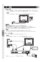
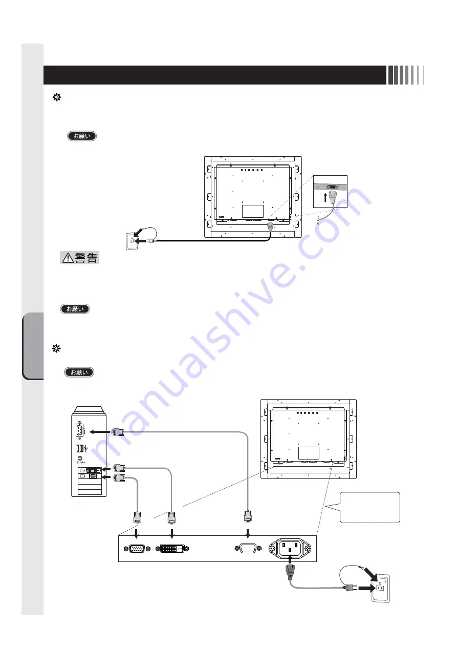
電源の接続

電源コンセントの周辺は、電源プラグの抜き差しが容易なようにしておいてください。
This socket-outlet shall be installed near the equipment and shall be easily accessible.

コンピュータに接続する前に、本機、コンピュータおよび周辺接続機器の電源を切ってください。

アースリード線を接地(アース接続)してから電源プラグをAC100V電源コンセントに接続してください。
コンピュータ本体の電源コンセントに接続するときは、電源容量を確認してください。(1.0A以上必要です。)

●表示された電源電圧以外で使用しないでください。火災・感電の原因になります。
●故障のとき感電の原因となりますので、電源プラグのアースリード線は必ず接地(アース)

してください。

また、電源プラグのアースリード線は電源コンセントに挿入または接触させないでください。火災・感電の原因となります。

●本機に添付している電源コードは本機専用です。安全のため他の機器には使用しないでください。

ケーブルの接続

ケーブルは、接続後必ずそれぞれの固定ネジで確実に固定してください。

ケーブルを接続する前に、本機、コンピュータおよび周辺機器の電源を切ってください。

アースリード線

電源コード

RS-232C

シリアルポート 

DVI出力 

VGA出力 

2

4

DVI-D

3

コンピュータ

ミニD-Sub 15

D-Sub 9 

DVI
入力

1

電源コード 

USBポート 

1:電源コード 
2:映像信号ケーブル(ミニD-Sub 15) 

3:映像信号ケーブル(DVI-D)
4:タッチ通信ケーブル(D-Sub 9) 

VGA
入力

RS232C

映像信号ケーブルは 
2または3どちらかのみ 
を接続します。 

Summary of Contents for TSD-CT194-MN

Page 1: ...2 3 6 6 7 7 OSD 8 8 8 9 9 9 14 14 16 16 17 17 18 19 11 11 11 12 http www mee co jp sales visual touch monitor 19 TSD CT194 MN...

Page 2: ...2 VCCI B VCCI WindowsNT Windows Vista Windows Microsoft Corporation Macintosh Apple Inc...

Page 3: ...3 AC100V AC100V...

Page 4: ...4 During servicing disconnect the plug from the socket outlet...

Page 5: ...5 This Touch monitor is designed for use in Japan and can not be used in any other countries 40 70cm OA...

Page 6: ...6 OSD OSD P10 MENU EXIT OSD OSD OSD OSD OSD 1 OSD SELECT SELECT INPUT OSD OSD OSD OSD SELECT P11 I...

Page 7: ...7 DVI D DVI D CAC DV2D 2m D Sub15 D Sub 9 RS 232C RS 232C D Sub 15 D Sub 15 2 CD ROM D sub 9 D sub 9 DVI D 24 DVI D DVI D...

Page 8: ...This socket outlet shall be installed near the equipment and shall be easily accessible AC100V 1 0A RS 232C DVI VGA 2 4 DVI D 3 D Sub 15 D Sub 9 DVI 1 USB 1 2 D Sub 15 3 DVI D 4 D Sub 9 VGA RS232C 2...

Page 9: ...0 80 0kHz 50 75Hz 1 1 2 OSD Auto Image Display Width Phase H Position V Position Auto Ad just Image DOS 2 1 2 OSD 3 SELECT INPUT SELECT INPUT OSD MENU EXIT OSD OSD OSD On Screen Display OSD Auto Adjus...

Page 10: ...trol Tool OSD Control Information Exit Brightness Contrast OSD OSD OSD OSD OSD Brightness Contrast Reset Bright Cont Exit Auto Color Color Temperature Exit Auto Image Display Width Phase H Position V...

Page 11: ...60 0Hz 2 640 x 480 37 9kHz 73 0Hz 3 640 x 480 37 5kHz 75 0Hz 4 720 x 400 31 5kHz 70 0Hz 5 800 x 600 37 9kHz 60 0Hz 6 800 x 600 48 1kHz 72 0Hz 7 800 x 600 46 9kHz 75 0Hz 8 1024 x 768 48 4kHz 60 0Hz 9...

Page 12: ...2000 Windows XP WindowsVista Windows 7 CD ROM CD ROM Windows 2000 Windows XP WindowsVista Windows 7 CD ROM Administrator Windows 3 1 WindowsNT 4 OS 2 Macintosh CD ROM CD ROM CD ROM CD ROM index html...

Page 13: ...13 WindowsXP TouchWare5 64SR5 2 4 5 6 7 4 5 5...

Page 14: ...14 WindowsVista Windows7 MT 7 Software Setup Type Typical Select Components Legacy mouse 8 9...

Page 15: ...15 4 3 6 5 1 2 7 8 1 1 P6 2 3 1 OSD Contrast Brightness OSD P9 2 1 P11 2 3 2 1 2 OSD Image Control Phase 3 60Hz 3 1 4 1 1...

Page 16: ...16 5 1 LED 2 3 OSD Color Control Color Temperature USER Tool Reset 6 1 7 1 AC100V 5 5 2 3 8 1 AC100V 5 5 2 3 CD ROM P12...

Page 17: ...17 TSD CT194 MN 1 1...

Page 18: ...18 9 2 TSD CT194 MN 1 TEL 1 2 3 1 2 3 4 5 4...

Page 19: ...75 85 CR 10 1024 H 1024 V RS232C 3ms 0 7Vp p RGB TTL 30 0kHz 80 0kHz 50Hz 75Hz 1670 1000 1 376 32 H mm 301 06 V mm 300cd m2 D Sub15 DVI D D Sub9 5 35 30 80 RH AC100 240V 50 60Hz 23W 31W VCCI B UL cUL...

Page 20: ...ition OSD Timer OSD V Position Phase Reset Resolution SELECT INPUT Sharpness TFT Tool USB Version VESA V Position 10 10 10 10 10 10 10 10 10 11 7 10 10 10 10 10 10 10 6 9 10 10 10 10 10 10 10 6 10 19...

Page 21: ...ustment OSD Function 6 Functions Automatic Screen Display Power Management Function Installation for Touch driver 7 Troubleshooting If the Device Malfunctions Cleaning Instructions 8 Addendum Specific...

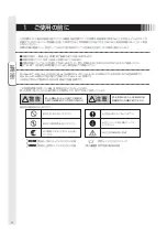
Page 22: ...outlet Be sure to follow the instructions Be sure to ground earth the earth wire Beware of high voltage indicated on the back surface of the unit The symbols used in this User s Manual and their mean...

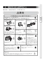
Page 23: ...designated power voltages may cause fire or electric shock This device comes with a power cord AC100V compatible with the power outlets in general households When operating at voltages other than AC10...

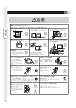
Page 24: ...ric shock Check that you have unplugged the power cable and disconnected the cables connecting the device to other machines before you move it Prohibited Hold the power plug firmly to unplug it Pullin...

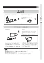
Page 25: ...screen display with Screen Saver etc Wipe the dust etc from the power plug regularly May cause fire Clean and inspect connection of your power plug once a year Remove dust For use in Japan only This t...

Page 26: ...is shown Decide which adjustment items you wish to select Button When the OSD screen is not shown HOT KEY function Shows the brightness adjustment screen When the OSD screen is shown After selecting...

Page 27: ...INPUT CONNECTOR Connects the power cord Use CAC DV2D 2m of Elecom Co Ltd for the DVI D cable Verifying Accessories These are the accessories that should come with your purchase If any of your accessor...

Page 28: ...power plug must be grounded Also never insert the grounding lead wire into or let the grounding lead wire touch the power outlet It causes the fire or the electric shock The power cord that comes wit...

Page 29: ...er is displayed while automatic screen adjusting This character disappears when automatic screen adjustment ends OSD function This product features OSD On Screen Display function to adjust the image o...

Page 30: ...on of the screen Displays the frequency of horizontal and vertical sync signals Displays the F W Version of the MCU End OSD adjustment Brightness Contrast Reset Bright Cont Exit Auto Color Color Tempe...

Page 31: ...e automatically saved Executing All Reset will erase all values saved in user memory This machine is compatible with horizontal frequencies of 30 0 80 0kHz and vertical frequencies of 50 75Hz However...

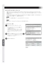
Page 32: ...ation for Touch driver The installation menu automatically appears after the accessory CD ROM is inserted to the CD drive If the installation menu does not appear automatically double click the icon o...

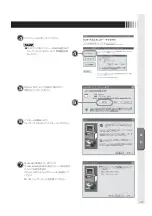
Page 33: ...rted Install refer to the User s Guide If Windows XP while installing a touch driver the window is displayed Click the 2 points calibration 2 button Installation is started Please refer the User s Gui...

Page 34: ...ion Refer to User s Guide 8 9 When the touch panel monitor is turned on the analog capacitive coupling method touch sensor executes initialization When the touch position is detected initialization in...

Page 35: ...e sure that your PC and equipment should be connected completely and correctly Power indicator is lit in ORANGE 1 Power management function may be operating To release it touch the screen on LCD panel...

Page 36: ...onds Some PCs cause the picture unstable for several seconds when its input sig nal is switched In such case your equipment has no problem 7 Touch panel does not respond 1 The controller located withi...

Page 37: ...a soft cloth when cleaning If the monitor is too soiled soak a cloth in synthetic detergent and give it a wring before cleaning Finish it with a dried soft cloth finally Avoid using any cleaning solu...

Page 38: ...376 32 H mm 301 06 V mm Luminance standard 300cd m2 Input output signal connectors Video signal Mini D sub 15 pins female DVI D female Touch communication signal D sub 9 pins male Environmental consid...

Page 39: ......

Page 40: ...40D871117B10...

Reviews: