EN
39
OIL
1. Remove the plastic oil filler screw on top
of the compressor housing crankcase.
2. Fill oil in the crankcase up to the middle of
the red circle in the level glass.
3. Screw in the new oil filler screw.
FIG. 4
AIR FILTER
WARNING!
The oil filter must be fitted before use.
Without an air filter the compressor will be
damaged and the warranty invalidated. The air
filter is screwed on the right side of the cylinder.
FIG. 5
USE
WARNING!
• Check the oil level before using for the
first time. The compressor will be
irreparably damaged and the warranty
invalidated if it used without oil.
• Never point the compressed air outlet at
your body or persons in the vicinity –
risk of personal injury.
• Do not inhale air from the compressor.
• Extension cords up to 25 m must have a
minimum cross-sectional wire area of 1.5
mm
²
.
• The connection and the repair of
electrical equipment must only be
carried out by an authorised electrician.
• Check the overpressure valve every day.
1. Check that the work area is clean, dry and
well ventilated.
2. Check that the oil level is correct and that
the air filter has been fitted.
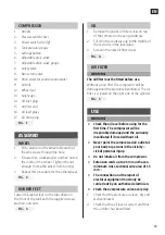
COMPRESSOR
1. Handle
2. Pressure switch cover
3. Power switch (On/Off)
4. Tank pressure gauge
5. Settings button
6. Adjustable drain valve
7. Adjustable drain valve gauge
8. Safety valve
9. Non-return valve
10. Drain screw for condensation water
11. Air tank
12. Wheel (x2)
13. Safety sign
14. Oil inlet plug
15. Air filter unit
16. Oil level glass
17. Oil drain plug
FIG. 1
ASSEMBLY
WHEEL
1. Put a washer on the wheel axle and put
the wheel axle through the hole.
2. Fit a washer, a lock washer and hex nut on
the inside of the wheel. Tighten the nut
enough to stop the wheel from turning.
3. Repeat this procedure for the other wheel.
FIG. 2
RUBBER FEET
Fasten the rubber feet on the tabs down on
the front of the tank with the supplied screws,
washers and nuts.
FIG. 3


