EN
40
WARNING!
• To read off the correct pressure air must
be flowing through the outlet.
• The adjustable valve must be adjusted
and the gauge checked when the valve
is open, while air is flowing through the
outlet and accessory. To increase the air
pressure, turn the valve clockwise. To
reduce the pressure, turn the valve
anticlockwise.
5. Switch off the product as described below
after use.
– Push down the power switch.
– Wait until the pressure is relieved
through the outlet valve under the
switch cover.
WARNING!
When the switch is pushed down you should
hear air flowing out for half a second.
6. Switch off the compressor and pull out
the plug.
7. Pull the ring on the safety valve to make
sure the tank is relieved of pressure, or
open the outlet tap on the tank to relieve
the pressure.
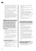
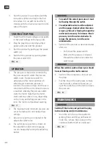
FIG. 8
MAINTENANCE
WARNING!
Switch off the motor and pull out the plug
before cleaning and/or maintenance.
1. Drain the oil in the crankcase after 10
working hours and fill up with new oil.
To do this, remove the oil plugs on the
crankcase (bottom left on crankcase).
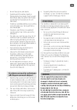
FIG. 9
3. Start the product in accordance with the
instructions. When starting for the first
time allow it to run with no load for 10
minutes with the drain valve open to lubri-
cate all the parts.
STARTING/STOPPING
1. Check that the mains voltage corresponds
to the rated voltage on the type plate.
2. Plug the plug into a correctly earthed
power point and start the product.
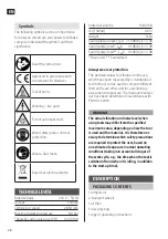
3. Start the product by pulling up the power
switch (A).
4. Switch off the product by pushing down
the power switch (B).
FIG. 6
OPERATION
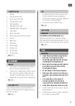
1. The pressure in the tank is controlled by
the pressure switch under the pressure
switch cover. The pressure switch is
activated and the motor switches off
when the set maximum pressure is
reached. The pressure drops and the air is
consumed until the set minimum pressure
is reached, whereby the pressure switch
starts the motor. Note that the motor
starts and stops when in use, depending
on the rising and falling pressure in the
tank. The motor starts without warning.
FIG. 7
2. The maximum and minimum pressure are
set at the factory. Do not change these
settings.
3. All accessory parts are connected to the
adjustable outlet valve.
4. The outlet pressure, which is shown on
the adjustable outlet pressure gauge,
can be changed by turning the adjusting
button.


