GB
EXTREMELY IMPORTANT
Read these safety instructions carefully in addition to the instructions for assembly, use, operation and maintenance and keep
them in a safe place for any subsequent consultation.
This transmission jack has been exclusively designed for use in transmissions or under elevated vehicles to remove, move or
install a gearbox. Any other application beyond the conditions established will be considered inappropriate.
Handle the jack correctly and ensure that all parts and components are in good condition prior to its initial and subsequent uses
and that no parts are missing. Otherwise, do not use the jack until the problem has been solved.
Operation, repair and maintenance of the jack should only be performed by authorised persons, having read carefully and
understood the contents of this manual and the assembly instructions.
Do not modify the jack in any way or use non-original components, which may damage the jack and invalidate the guarantee.
Non-compliance with these instructions may result in injury or damage to the user, the jack or the gearbox or elements that are
removed or reinstalled.
The manufacturer accepts no responsibility for the improper use of the transmission jack.
1.
SAFETY INSTRUCTIONS
1.1.
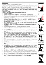
The weight of the element to be removed, moved or installed should never exceed the rated capacity of the jack.
1.2.
The maximum stroke of the jack, indicated on the label, should never be exceeded.
1.3.
The jack should be supported on a solid, level and horizontal surface to avoid any sinking. The work area should be well
illuminated and free of unnecessary elements. Non authorised personnel should keep a safe distance from the jack during
its operation.
1.4.
The vehicle from which the gearbox is to be removed or another component is to be installed should have the hand brake
applied and should be lifted to a sufficient height to allow the jack to be introduced. Mechanical support stands will be
used or another appropriate method to ensure that the correct position cannot be moved.
Stand outside the load
perimeter. There should be nobody inside the vehicle.
1.5.
Prior to proceeding with the lowering, installation or movement of the gearbox, it must be secured and centred on the
lifting support.
1.6.
Although the jack is not a transportation element, it may be necessary to move the load, and therefore the floor surface
should not be slippery and should be free from obstacles so as to avoid any overturning. With the load centred and
secured, position the piston of the jack at its minimum height for transportation.
1.7.
During lifting, lowering or transportation, all safety precautions should be taken to avoid the displacement of the load. If
the jack tilts or sways during the operation, maintain a safety distance and do not attempt to hold it steady.
1.8.
The jack is a lifting device and should never be used to support a load.
1.9.
As a safety measure against overload, the jack is fitted with an overload valve, set at the factory. This valve should not be
tampered with under any circumstances.
2.
USE AND OPERATION
2.1.
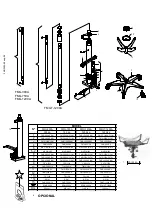
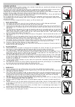
Having checked that no component is missing, position the hydraulic unit (15) over the base (11), securing it with the
three screws ( 5) that are supplied, and position the support stand (12) over the extreme of the piston (1).
2.2.
Prior to using the jack, it is necessary to drain the hydraulic circuit to eliminate any air from the valve system.
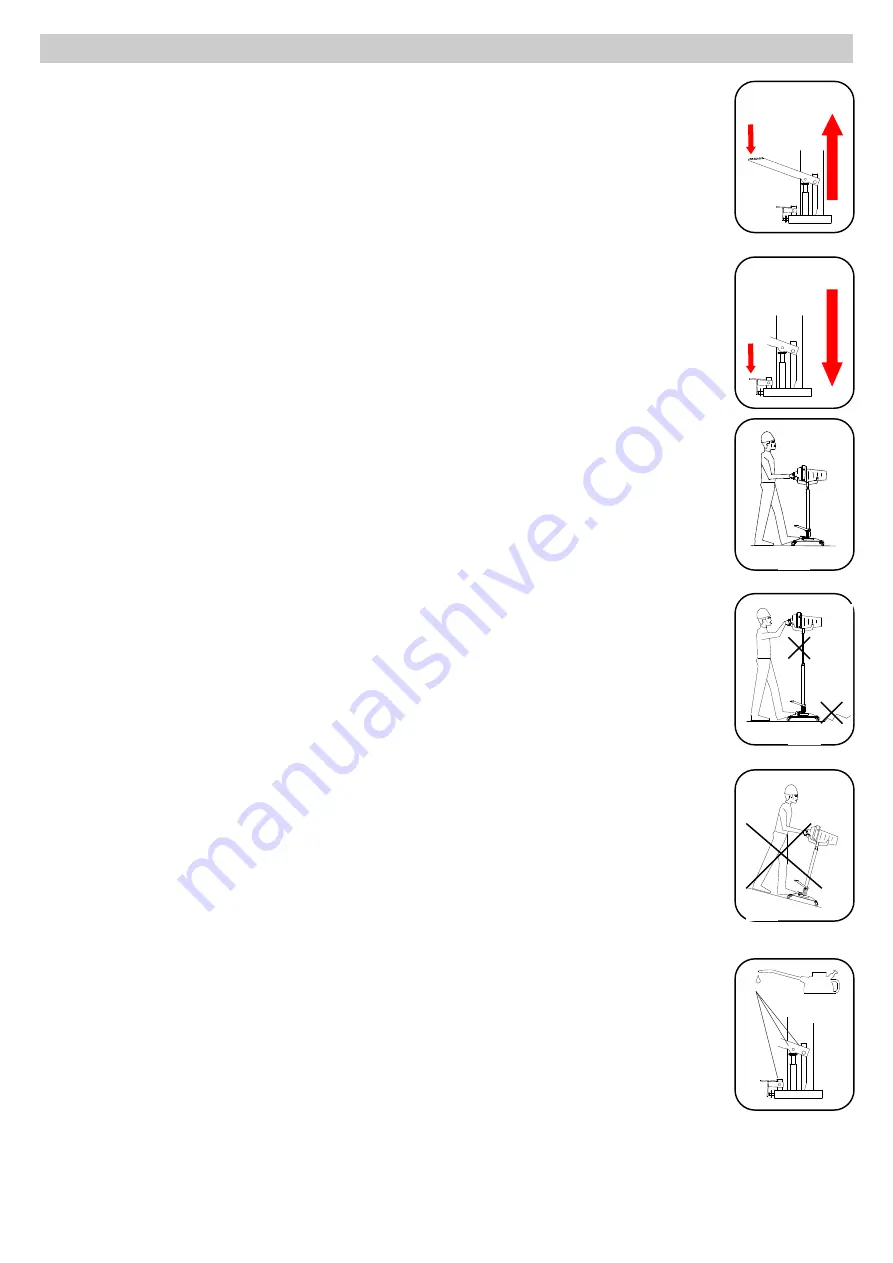
To simplify the operation, the help of another person is recommendable to apply pressure on the release pedal (7,Fig.2).
Simultaneously, hold the jack by the handle (8) and then proceed to apply pressure on the lifting pedal (6,Fig,1). By
releasing the release pedal (7,Fig 2), the jack is ready for operation.
2.3.
The jack is lifted by applying pressure on the pedal (6,Fig.1) and lowering by applying pressure on the release pedal
(7,Fig 2). Fix the position of the jack in relation to the gearbox or element to be removed so that when the piston is lifted,
the stand (12) is centred. Prior to proceeding with the lowering, installation or movement of the gearbox, it is necessary
to secure it on the lifting stand.
2.4.
To avoid brusque lowering operations, the jack is fitted with a system which automatically regulates and controls the
lowering operation (L.C.S.).
2.5.
Prior to each use, check for bent, broken, cracked or loose parts and withdraw the jack from service if it is suspected that
the jack has been subjected to abnormal loads or has suffered any knocks.
2.6.
Once the jack has been used, the piston should be fully retracted to avoid corrosion
3.
MAINTENANCE
3.1.
Both the maintenance and repair of this jack may only be carried out by qualified and authorized personnel.
3.2.
Clean and lubricate the moving parts of the jack at regular intervals. The whole jack should be kept clean and protected
from aggressive conditions at all times.
3.3.
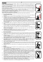
If the oil level needs to be checked or refilled, proceed as follows: With the jack in the vertical position and the piston fully
retracted, remove the filler plug, which is indicated with a star, and drain its contents into a container. Position the jack in a
horizontal position; proceed to introduce the necessary volume as indicated in the table. Then reinsert the filler plug.
Important
: An excess of oil over the volume required may affect the operation of the jack.
3.4.
Only use hydraulic oil, HL or HM type, with an ISO grade of cinematic viscosity of 30cSt at 40ºC or of an Engler viscosity
of 3 at 50ºC.
Extremely important: Never use brake fluid.
3.5.
Following a period of prolonged intensive use, it is recommendable to change the oil in order to extend the useful life of
the jack.
3.6.
When the jack is not in use, the piston should be fully retracted to avoid corrosion. However, it is recommendable to apply
an anti-corrosion product to the main piston and particularly to the pump. Store the device in a dry, clean place, out of the
reach of children.
3.7.
At the end of the useful life of the jack, drain off the oil and hand it over to an authorised agent and dispose of the
remaining parts in accordance with local regulations.
3.8.
Both the repair kit, which exclusively contains the retainers and joints of the hydraulic unit and the spare part sets must be
ordered using the reference assigned in the table.
2
OK
3
NO
4
1
OIL
NO
5


