Installation guide solar modules
V1 – April 2015
11 - 19
4.7
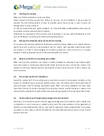
Install the module in an area free of shade:
Even a low degree of shading will have a negative effect on the system yield. Therefore, the system must be
installed in a location without shading. The module should never be shaded completely during the whole
year
.
4.8
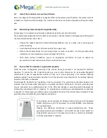
Maximizing Power Output through Bifaciality
Output power in increased proportionally to albedo received by rear side of modules
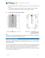
The available albedo light that hits the back of the module is directly related to the height (and tilt angle) of
the module installed over the surface.
o
Choose the highest possible Surface Reflectivity/Albedo
, such as a white roof or white ground
surface covering.
o
Avoid shading the back side of the module by the support rack.
o
Elevate the modules above the mounting surface as much as possible. For flat ground/rooftop
installation it’s recommended a minimum height of 50-70 cm
o
With tilted rooftop installation, ensure an appropriate ventilation on back to reduce an
accumulation of heat with adverse effects on the performance.
4.9
Ensure that the modules are grounded properly:
Under the terms of MegaCell, grounding of the module frame (if present) is not required for fault-free
operation. To reduce the risk of electric shock (e.g. due to static charge) as far as possible, MegaCell
recommends to ask an experienced installer to carry out a proper grounding. If an external lightning
protection system has been already installed, the PV system has to be integrated in the existing lightning
protection concept by a specialist.
Country-specific standards and regulations must be observed. The grounding connections between the
modules must be checked and accepted by a qualified electrician. Furthermore, the main grounding may
only be connected by a qualified electrician. In the USA and Canada, a grounding method approved by
Underwriters Laboratories (UL) is obligatory. To provide proper grounding, an optimal electrical conductivity
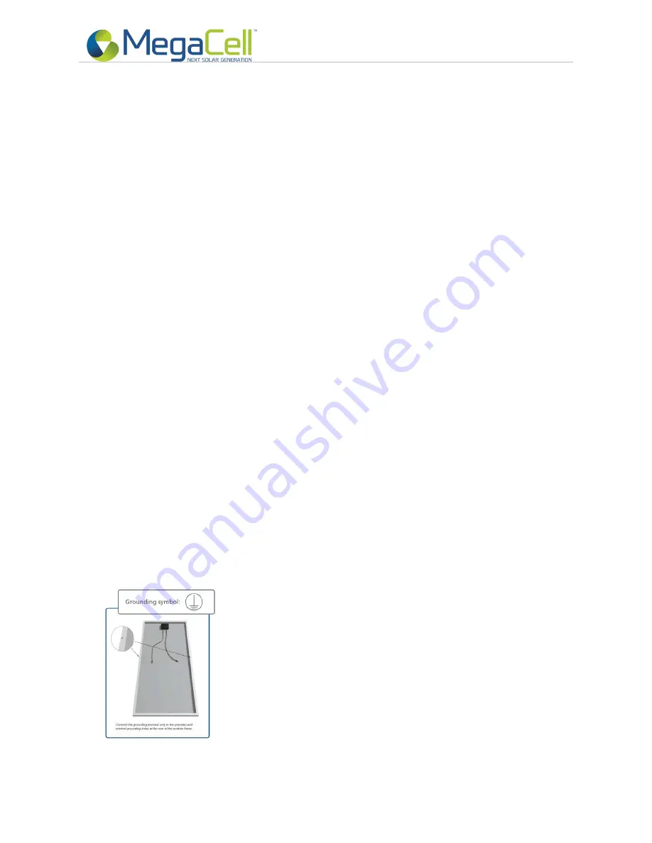
is required. For this purpose, grounding holes are provided at the rear of the module frame (if present).These
grounding holes are marked by a stamped ground symbol.
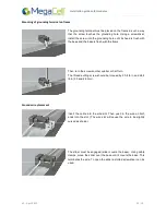
For grounding we recommend the Solklip grounding terminal with integrated
thread cutting screw, (UL 467 approved, UL number E69905), manufactured
by Tyco Electronics.
Observe the additional instructions at www.tycoelectronics.com. These
grounding terminals accommodate 4 mm² (AWG 12) and 6 mm² (AWG 10)
stripped solid copper wires. The wires must not be cut, notched or scratched.
No further preparation is required.
Summary of Contents for MBA-GG60 BiSoN Series
Page 2: ......
Page 4: ...Installation guide solar modules V1 April 2015 4 19...

