background image


Installation guide solar modules 


V1 – April 2015 

14 - 19 


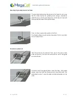
The obligatory position of the clips along the frame depends on which side of the module is used for the 

installation. 

Note  that  on  both  sides  of  the  module  the  pressure  clamps  always  should  be  mounted  in  a  symmetric 

position with respect to the center line for a proper load distribution.  

Clamps  must  be  installed  according  to  the  manufacturer’s  specific  instructions.  Do  not  apply  excessive 

pressure on the frame such that the frame deforms. MegaCell recommends a torque of approximately 10 

Newton meter [Nm], but refer to the clamp manufacturer for specific hardware and torque requirements. 

For a safe and effective installation of MegaCell framed modules, the lengths for the pressure clamps are 

strongly recommended is not less than 50 mm for 60 - 156 x 156 mm cell modules. 

The minimum recommended clamp thickness is 2,5 mm 

The clamps should have contact only with the module frame and, to avoid shadowing effects and possible 

damage, should not overlap onto or over the module glass. 

Do not install the modules with pressure clamps mounted out of the specified areas, otherwise the module 

mechanical resistance may be affected. 

Use of unauthorized laminate clamps will render the product and performance warranty void 
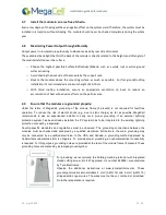
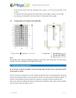
 

5.2


Frameless modules 

The  use  of  frameless  MegaCell  modules  requires  frameless  mounting  system  that  grabs  the  edge  of  the 

module with a pressure clamp that is lined with rubber pads (EPDM, etc). 

 The clamps must overlap from the edge of the module by at least 10mm but should avoid shading the cells 

in  the  module.  The  applied  torque  used  to  attach  the  clamps  to  the  module/racking  should  refer  to  the 

mechanical design standard for the specific bolt in use.  

For 4 point mounting, 4 mounting clamps should be located as described on paragraph 5.4  


Depending  on  local  snow  and  wind  conditions,  more  than  4  clamps  may  be  needed  to  ensure  that  the 

modules can withstand the expected load. For loads larger than 4000Pa (50psf), ensure that each clamp has 

a  minimum  length  of  120mm.  Do  not  use  clamps  with  a  length  smaller  than  80mm  unless  approved  by 

MegaCell. 


When installing modules in an array, please allow for a minimum lateral air gap of at least 10mm between 

the exposed edges of the adjacent modules to account for thermal expansion and contraction of PV system 

elements in the field. 


5.3


Frameless modules: continuous mounting (Carports, BIPV, etc.)  

For a continuous mounting system where the entire perimeter of the module is used, the mounting surface 

that contacts the module should:  

o


Be a rubber material (such as EPDM, etc.) on all surfaces making contact with the module.  

Summary of Contents for MBA-GG60 BiSoN Series

Page 1: ...Document name MCELL_PV_Modules_Installation_Manual_EN_v1 2_20150715 Revision date V1 2 July 2015 www megacell it SAFETY AND INSTALLATION MANUAL BIFACIAL SOLAR MODULES...

Page 2: ......

Page 3: ...allowable maximum mechanical loading 10 4 4 Make sure that the surroundings are suitable 10 4 5 The correct location for installation 10 4 6 Yield maintenance through optimal alignment and inclination...

Page 4: ...Installation guide solar modules V1 April 2015 4 19...

Page 5: ...Installation guide solar modules V1 April 2015 5 19 1 MODULES 1 1 MBF GG60 BiSoN series with frame 1 2 MBA GG60 BiSoN series frameless...

Page 6: ...oduct are beyond company control MegaCell does not assume responsibility and expressly disclaims liability for loss damage or expense resulting from improper installation handling or use The informati...

Page 7: ...d after installation to calculate correctly inverter cables and connection size Serial number Each individual module is identified by a unique serial number accompanied with a barcode They are permane...

Page 8: ...r modules generate electricity When exposed to light a voltage occurs which can be dangerous and life threatening Even though the individual modules generate a relatively low voltage of 50 V DC the vo...

Page 9: ...and safe unpacking Please refers to the instructions printed on the cartoon box of each pallet The modules are sensitive technical components which must be handled with utmost care Therefore be partic...

Page 10: ...re that after installation the module is neither subjected to artificially concentrated sunlight immersed in water or continuously splashed with liquids By all means make sure that the module is not s...

Page 11: ...f the module frame if present is not required for fault free operation To reduce the risk of electric shock e g due to static charge as far as possible MegaCell recommends to ask an experienced instal...

Page 12: ...ith the frame Then turn the screw another quarter or half turn The thread cutting screw should be torqued by 20 4 lb in and 24 8 lb in 2 3 and 2 8 Nm Ground wire placement Insert the cable into the wi...

Page 13: ...hould not be mounted in such a way that the drain holes of the module can become blocked MegaCell PV modules are suitable for mechanical mounting both in portrait and landscape orientation In choosing...

Page 14: ...will render the product and performance warranty void 5 2 Frameless modules The use of frameless MegaCell modules requires frameless mounting system that grabs the edge of the module with a pressure...

Page 15: ...snow load zones the terrain category and the height of the building 6 ELECTRICAL INSTALLATION Do not connect or disconnect modules under load Danger Risk of serious injury or death from electric shock...

Page 16: ...ed against reverse polarity o Keep the total area of all conductor loops as low as possible in order to reduce the voltages due to indirect lightning strikes o Always carry out a careful final check o...

Page 17: ...LES MegaCell recommends to inspect the installation on a regular basis with following minimum maintenance o Check the electrical and mechanical connections to verify that they are clean secure and und...

Page 18: ...sual appearance of the module surface and result in decreased performance o Use of automatic cleaning machines for solar energy systems is at your own risk and is not authorized by MegaCell in any way...

Page 19: ...Document name MCELL_PV_Modules_Installation_Manual_EN_v1 2_20150715 Revision date V1 2 July 2015 www megacell it MegaCell S r l a socio unico A coordinated company part of Mega Group S r l Registered...

Reviews: