background image

to check the system.


Do not tamper with any of the safety valves fitted to the system. If a fault is

suspected

contact a competent installer.


DO NOT bypass the thermal cut-out(s) in any circumstances.

page 4


3. Technical specifications

3.1 Technical data

Table 1: Technical data - Solar


Solar 800i Solar 1000i

Max direct kW rating 6 6

Aux Coil surface area m21.5


Aux Coil rating (kW) 15l/min 25.1 26.6

30l/min 37.2 38.3

60l/min 47.5 45.8

Aux coil heat up time (mins) 15l/min 64.2 74.5

30l/min 44.6 54.1

Summary of Contents for Eco Plus Solar

Page 1: ...36006204_issue_03 Megaflo Eco Plus Solar Product Guide Megaflo Eco Plus Solar Unvented Hot Water Cylinders 800L 1000L ...

Page 2: ... 3 Abbreviations 1 4 Liabilities 2 Safety 2 1 General safety warnings 2 2 Recommendations 2 3 Specific safety instructions 3 Technical specifications 3 1 Technical data Dimensions and connections Electrical diagram 4 Description of the product 4 1 General description 4 2 Operation principle 4 3 Main components 4 4 Standard delivery 5 Before installation 5 1 Installation regulations 5 2 Installatio...

Page 3: ...llation 7 Commissioning 7 1 General 7 2 Checklist before commissioning 7 3 Commissioning procedure 8 Operation 8 1 General 9 Maintenance 9 1 General 9 2 Standard inspection maintenance operations 10 Troubleshooting 10 1 Fault finding 11 Decommissioning 11 1 Decommissioning procedure 12 Spare parts 12 1 Spare parts list Benchmark checklist Service records Guarantee ...

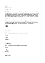
Page 4: ...lding Regulation P5 Northern Ireland and the Water Fitting Regulations England and Wales or Water Byelaws Scotland 1 2 Symbols used In these instructions various risk levels are employed to draw the user s attention to particular information In doing so we wish to safeguard the user avoid hazards and guarantee the correct operation of the appliance DANGER Risk of a dangerous situation causing seri...

Page 5: ...efore subject to change without notice Our liability as the manufacturer may not be invoked in the following cases Failure to abide by the instructions on using the appliance Faulty or insufficient maintenance of the appliance Failure to abide by the instructions on installing the product Installer s liability The Installer is responsible for the installation and the commissioning of the appliance...

Page 6: ...struction manuals in good condition and close to the appliance This appliance can be used by children aged 8 years and above and persons with reduced physical sensory or mental capabilities or lack of experience and knowledge if they have been given supervision or instruction concerning use of the appliance in a safe way and understand the hazards involved Children shall not play with the applianc...

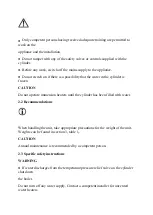
Page 7: ...er is frozen CAUTION Do not operate immersion heaters until the cylinder has been filled with water 2 2 Recommendations When handling the unit take appropriate precautions for the weight of the unit Weights can be found in section 3 table 1 CAUTION Annual maintenance is recommended by a competent person 2 3 Specific safety instructions WARNING If water discharges from the temperature pressure reli...

Page 8: ...T bypass the thermal cut out s in any circumstances page 4 3 Technical specifications 3 1 Technical data Table 1 Technical data Solar Solar 800i Solar 1000i Max direct kW rating 6 6 Aux Coil surface area m21 5 Aux Coil rating kW 15l min 25 1 26 6 30l min 37 2 38 3 60l min 47 5 45 8 Aux coil heat up time mins 15l min 64 2 74 5 30l min 44 6 54 1 ...

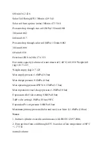
Page 9: ...ht full kg 1017 1225 Weight empty kg 217 225 Max supply pressure 1 6MPa 16 bar Max design pressure 0 8 MPa 8 bar Max operating pressure PRV 0 35MPa 3 5 bar Max expansion vessel charge pressure 1 0MPa 10 bar Expansion relief valve setting 0 8MPa 8 bar T P valve setting 1 0MPa 10 bar 90 C Expansion Prv set pressure 0 8MPa 8 bar Maximum primary pressure Solar and Aux see Note 3 1 0MPa 10 bar Notes 1 ...

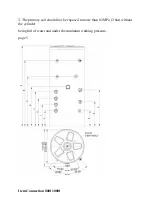
Page 10: ...3 The primary coil should not be exposed to more than 0 3MPa 3 bar without the cylinder being full of water and under the minimum working pressure page 5 Item Connection 800l 1000l ...

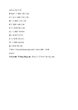
Page 11: ...218 1538 D1 BSP 1138 1338 E BSP 1049 1249 F1 BSP 998 1198 G1 BSP 798 998 H BSP 710 710 I1 BSP 623 623 J1 BSP 448 448 K1 BSP 438 438 Table 3 General dimensions table Solar 800l 1000l page 6 Schematic Wiring Diagram Basic 2 x 2 Port Valve System ...

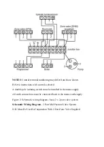
Page 12: ...pole isolating switch must be installed in the mains supply All earth connections must be connected back to the mains earth supply Figure 2 Schematic wiring diagram basic 2 x 2 port valve system Schematic Wiring Diagram 3 Port Mid Position Valve System N B Must Be Used In Conjunction With 2 Port Zone Valve Supplied ...

Page 13: ... selected A double pole isolating switch must be installed in the mains supply All earth connections must be connected back to the mains earth supply Figure 3 Schematic wiring diagram 3 port mid position system page 7 6kW immersion Step 1 remove 4 retaining screws and lift lid off immersion heater ...

Page 14: ...Step 2 remove 2 screws holding thermostatic controls and slide out thermostat from stat pocket Step 3 Wire up immersion as per figures 6 ...

Page 15: ...e Pole 16A per pole contactors for 3 phase For signal wire use 5 core 1mm2 Fused at max 6A for thermostat and thermal cut out controls Disconnection time of the circuit protective device must be maintained below the regulatory minimum in the UK 5 seconds for fixed equipment cable sizes may have to be higher depending on the characteristics of the installation supply Step 4 Replace thermostatic con...

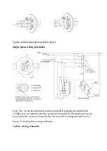
Page 16: ...ternal contactors must be approved components certified for 10 000 cycles of operation for the contactor controlled by the thermostat and at least 30 for the contactor controlled by the non self resetting thermal cut out Figure 5 Single phase wiring schematic 3 phase wiring schematic ...

Page 17: ...Figure 6 Three phase wiring schematic page 9 ...

Page 18: ...f the product 4 1 General description This product is a purpose designed unvented water heater The unit has a stainless steel inner vessel which ensures an excellent standard of corrosion resistance The outer casing is a combination of resilient thermoplastic ...

Page 19: ...Gas Oil or Electric To provide pressure to the tap or shower an unvented unit uses the incoming mains water pressure To do this the cylinder is sealed and not vented However when the volume of water is heated it expands and without any room for expansion could cause the cylinder to rupture and fail To allow expansion of this heated water it is important that an expansion vessel is used This vessel...

Page 20: ...lding Regulations Northern Ireland I E E Electrical Regs UK Water Regulations 5 2 Installation requirements Water supply In an unvented system the pressure and flow rate is directly related to the incoming water supply For this reason it is recommended that the maximum water demand is assessed and the water supply checked to ensure this demand can be satisfactorily met We suggest the minimum suppl...

Page 21: ...ittings pipework and connections must have a rated pressure of at least 8 bar dependant on cylinder being fitted at 80 C Limitations The cylinder should not be used in association with any of the following Solid fuel boilers or any other boiler in which the energy input is not under effective thermostatic control unless additional and appropriate safety measures are installed Ascending spray type ...

Page 22: ... cold temperatures will be experienced All exposed pipe work should be insulated The discharge pipework from the safety valves must have minimum fall of 1 200 from the unit and terminate in a safe and visible position Access to associated controls and immersion heaters must be available for the servicing and maintenance of the system Where these controls are installed against a wall a minimum dist...

Page 23: ...sported in an area free from excessive damp or humidity The Unit should be stored in a frost free environment To aid installation the water heater 800ltr upwards is provided with lifting points located at the top of the unit To access the lifting eyes please remove the top cover ...

Page 24: ...e feed and expansion cistern head above the cylinder should not exceed 2 5m Can be a sealed system or open vented type maximum primary pressure 3 bar The boiler cannot be vented through the cylinder 6 2 Water connections WARNING Under no circumstances should the factory fitted temperature pressure relief valve be removed other than by a competent person To do so will invalidate any guarantee or cl...

Page 25: ...also provided in figure 14 All pipe fittings are made via BSP female pipe connections directly to the unit A stopcock or servicing valve should be incorporated into the cold water supply to enable the cylinder and its associated controls to be isolated and serviced not supplied Figure 11 Typical installation schematic not to scale page 15 ...

Page 26: ...e core unit and expansion relief valve The valve can be fitted in any orientation to suit the installation as long as the valve is installed with the direction of flow arrows pointing in the correct direction The expansion relief valve should be installed with the discharge pipework in either the horizontal position or facing downwards No other valves should be placed between the cold water combin...

Page 27: ...perature should be set to 82 maximum flow temperature to auxiliary heat exchanger 89 C page 16 Secondary circulation If secondary circulation is required it is recommended that it be connected to the cylinder as shown see figure 13 below The secondary return pipe should be in 28mm pipe and incorporate a check valve to prevent backflow ...

Page 28: ...0 litres 18m Note Plastic pipe capacities may be reduced due to thicker wall sections In direct electric installations where a secondary circulation is required particular attention should be paid by the Installer to maintain the returning water temperature guidelines state that a minimum of 55 C return temperature is advisable Factors such as but not limited to secondary circulation flow rates mi...

Page 29: ...s conveyed to where it is visible but will not cause danger to persons in or about the building The tundish and discharge pipes should be fitted in accordance with the requirements and guidance notes of Building Regulation G3 The G3 Requirements and Guidance section 3 50 3 63 are reproduced in the following sections of this manual For discharge pipe ...

Page 30: ...f valves or combined temperature and pressure relief valves specified in 3 13 or 3 17 should discharge either directly or by way of a manifold via a short length of metal pipe D1 to a tundish 3 51 The diameter of discharge pipe D1 should be not less than the nominal outlet size of the temperature relief valve 3 52 Where a manifold is used it should be sized to accept and discharge the total discha...

Page 31: ... least one pipe size larger than the nominal outlet size of the safety device unless its total equivalent hydraulic resistance exceeds that of a straight pipe 9m long i e for discharge pipes between 9m and 18m the equivalent resistance length should be at least two sizes larger than the nominal outlet size of the safety device between 18 and 27m at least 3 sizes larger and so on bends must be take...

Page 32: ...d to the stack it may be possible to route a dedicated pipe alongside or in close proximity to the discharge stack Termination of discharge pipe 3 61 The discharge pipe D2 from the tundish should terminate in a safe place where there is no risk to persons in the vicinity of the discharge 3 62 Examples of acceptable discharge arrangements are a to a trapped gully with the end of the pipe below a fi...

Page 33: ...8m each 3 2m Therefore the permitted length equates to 5 8m 5 8m is less than the actual length of 7m therefore calculate the next largest size Maximum resistance allowed for a straight length of 28mm pipe D2 from a G temperature relief valves equates to 18m Subtract the resistance of 4 No 28mm elbows at 1 0m each 4 0m Therefore the maximum permitted length equates to 14m As the actual length is 7...

Page 34: ...esistance Created By Each Elbow Or Bend G 15mm 22mm 28mm 35mm up to 9m up to 18m up to 27m 0 8m 1 0m 1 4m G 22mm 28mm 35mm 42mm up to 9m up to 18m up to 27m 1 0m 1 4m 1 7m G1 28mm 35mm 42mm 54mm up to 9m ...

Page 35: ...up to 18m up to 27m 1 4m 1 7m 2 3m Figure 14 Typical discharge pipe arrangement extract from Building Regulation G3 Guidance Section 3 50 page 20 ...

Page 36: ...eaters are fitted with a dual thermostat and thermal cut out and must be wired in accordance withfigures 5 6 depending a single phase or 3 phase installation Space and heating systems controls The controls provided with the cylinder will ensure the safe operation of the unit within the central heating system Other controls will be necessary to control the space heating requirements and times that ...

Page 37: ...ng a suitable proprietary solar differential temperature controller The cylinder temperature sensing probe usually supplied with the solar differential temperature controller should be inserted into the pocket provided on the Solar cylinder and its cable secured using the cable clamp supplied The solar controller and solar primary circulation pump must be wired via the over temperature cut out mou...

Page 38: ...sensor pockets for use with solar controllers Figure 15 Solar wiring lay out page 22 7 Commissioning 7 1 General After filling the installation with water in the previous section please follow the following steps to complete the installation of the unit ...

Page 39: ...ter Switch on electrical supply to the immersion heater and allow the cylinder to heat up to normal working temperature 65 C recommended If necessary the temperature can be adjusted by inserting a flat bladed screwdriver in the adjustment spindle on front of the immersion heater thermostat and rotating The adjustment represents a temperature range of 15 C to 74 C Check the operation of thermostat ...

Page 40: ...the solar primary circuit is controlled by the solar differential temperature controller refer to the manufacturer s installation instructions for details of how to set up and commission the solar primary circuit The solar controller should be programmed to give a maximum storage temperature in the Megaflo eco Solar of 70 C although 65 C is recommended to minimise scaling WARNING If the unit is to...

Page 41: ... the UK and to encourage regular servicing to optimise safety efficiency and performance Benchmark is managed and promoted by the Heating and Hotwater Industry Council For more information visit www centralheating co uk Please ensure that the Installer has fully completed the Benchmark Checklist and that you have signed it to say that you have received a full and clear explanation of its operation...

Page 42: ...n heaters are fitted with a dual thermostat and cut out figure 6 Access to the thermostat can be made by opening the immersion heater cover DISCONNECT THE ELECTRICAL SUPPLY BEFORE OPENING THE COVER S Temperature adjustment is made by rotating the adjustment knob on the top of the thermostat The adjustment represents a temperature range of 15 C to 74 C Maximum working temperature is 74 C 165 F In v...

Page 43: ...ater systems have a continuing maintenance requirement in order to ensure safe working and optimum performance It is essential that the relief valve s are periodically inspected and manually opened to ensure no blockage has occurred in the valves or discharge pipework Maintenance of this appliance should only be carried out by a suitably qualified person Failure to do so could invalidate the warra...

Page 44: ...r Replace the strainer and screw the Pressure Reducing Valve cartridge into the moulded housing Close hot tap turn on isolating valve or main stop cock to the system Check for leaks Descaling immersion heater s Turn off the mains water supply isolate the electrical supply and turn off boiler Attach a hosepipe to the drain cock having sufficient length to take water to a suitable discharge point be...

Page 45: ... heater housing cover s Expansion vessel charge pressure Remove the dust cap on top of the vessel accordance with the inlet pressure set on the pressure reducing valve If it is lower than the required setting it should be re charged using a tyre pump Schrader valve type CAUTION DO NOT OVER CHARGE Re check the pressure and when correct replace the dust cap page 25 Re commissioning Check all electri...

Page 46: ...t persons in the installation and maintenance of unvented water heating systems Any spare parts used MUST be authorised parts Disconnect the electrical supply before removing any electrical equipment covers NEVER bypass any thermal controls or operate system without the necessary safety valves Water contained in the cylinder may be very hot especially following a thermal control failure Caution mu...

Page 47: ... is cold Direct immersion heater not switched on Check and switch on Direct immersion heater thermal cut out has operated Check reset by pushing button on thermostat Indirect programmer set to central heating only Check set to domestic hot water programme Indirect boiler not working Check boiler operation If fault is suspected consult boiler manufacturer s instructions Indirect thermal cut out has...

Page 48: ...ducing valve cartridge Remove expansion valve cartridge check condition of seat If necessary fit new expansion valve Water discharges from T P relief valve Thermal control failure CAUTION Water will be very hot Switch off power to immersion heater s and shut down boiler DO NOT turn off water supply When discharge stops check all thermal controls replace if faulty Milky waterOxygenated water Water ...

Page 49: ...ion is by means of an approved CFC HCFC free polyurethane foam with an ozone depletion factor of zero 12 Spare parts 12 1 Spare parts list A full range of spare parts are available for the cylinder range Refer to the Technical Data label on the unit to identify the model installed and ensure the correct part is ordered Table 8 Spares DESCRIPTION SPARES NUMBER 1 Integrated inlet control valve set 2...

Page 50: ...10 9 Temperature Pressure relief valve 95605103 10 Expansion vessel 60L 95607445 11 Tundish 22mm 28mm 95607367 12 2 port motorised valve 28mm 95605884 13 Blanking stat pocket 95607690 14 Isolating ball valve 1 95605178 15 Isolating drain valve 1 95605182 16 Cut out thermostat solar 95612652 page 28 ...

Page 51: ...page 29 Commissioning service records ...

Page 52: ......

Page 53: ...Indirect Model s 800 1000 Energy efficiency class C C Storage volume V in litres 800 0 1000 0 Standing loss in W 114 0 139 0 ...

Page 54: ... date of purchase of the Megaflo product that includes both parts and labour All other components including any other valves fittings and controls are covered by a two year warranty from the date of purchase of the Megaflo product that includes both parts and labour In the case of the Megaflo Systemready Megaflo Systemfit and Megaflo SolaReady units the supplied pumps and motorized valves where fi...

Page 55: ...ations outside of the United Kingdom and the Republic of Ireland please telephone Megaflo Export on 44 1603 420271 for further details of the warranty terms and conditions applicable These guarantees are valid provided that The Megaflo product has been installed by a competent Installer in accordance with the instructions contained in the installation instructions and in compliance with all releva...

Page 56: ...one by telephone online or by using the registration form provided with the product Evidence of purchase for example a receipt or delivery note and date of supply is submitted when making a claim The Megaflo product has not been affected by any cause beyond our reasonable control including without limitation an act of God explosion flood fire or accident war or civil disturbance strike industrial ...

Page 57: ...oint a contractor to carry this work out Heatrae Sadia accepts no liability for any third party damage These warranties do not affect your statutory rights and remedies in relation to the Megaflo products Annual service Annual services are available from Baxi Commercial the service division of Heatrae Sadia Please contact Baxi Commercial on 0345 0701058 for details In domestic properties lifetime ...

Page 58: ...r via www heatraesadia com Megaflo Heatrae Sadia Hurricane Way Norwich Norfolk NR6 6EA Megaflo may introduce modifications to their products from time to time Consequentially the details given in this brochure are subject to alteration without notice Specification Advice Hotline T 01603 420220 F 01603 420229 E specifier heatraesadia com www heatraesadia com Heatrae Sadia is a trading name of Baxi ...

Page 59: ...Megaflo Hurricane Way Norwich Norfolk NR6 6EA 36006204_issue_03 ...

Reviews: