COMMISSIONING
32
Thermostat (heating)
The thermostat is an independent control circuit from the storage loading. Thus, auxiliary heating of the top area of the
storage cylinder is made possible.
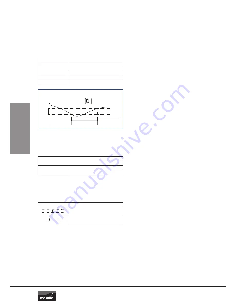
The output A3 will be (see Fig 29):
• Switched on, when the temperature falls below the adjusted start level.
• Switched off, when the temperature reaches the adjusted start level + hysteresis.
Tube collector
The function “tube collector” can be switched off/on in the “Basic setting” menu – point 4. Timeframe 4 in the “Program”
menu makes it possible to activate this function during certain periods of the day. When activated, the solar pump will be
switched on every 30 minutes for a period of 30 seconds to check for any heat gain in the collector.
Sensor monitoring
The sensors and their connecting cables are constantly monitored for any break or short circuit. If a faulty sensor is detected
by the controller, the symbol is shown. By scrolling up and down you can detect the source of the error.
The use of the wrong type of temperature sensors can also give to an error message
Corresponding values in menu
"Basic adjustment"
"Programming"
14 -- 2
Start temperature max ºC
15 -- 5
Hysteresis dT in K
Time period (1...3) Start: min time
Time period (1...3) Stop: min time
33
© Baxi Heating UK 2012
“Basic adjustment”
“Programming”
14 -- 1
Start temperature max ºC
15 -- 5
Hysteresis dT in K
Time period (1…3) Start: min time
Time period (1…3) Stop: max time
Corresponding values in menu
“Basic adjustment”
“Programming”
14 -- 2
Start temperature max ºC
15 -- 5
Hysteresis dT in K
Time period (1…3) Start: min time
Time period (1…3) Stop: max time
Corresponding values in menu
“Basic adjustment”
“Programming”
---
Rotational speed min <100%
Corresponding values in menu
Thermostat
(Storage top)
Heating on (A3)
T[ºC]
t
dT
10k
TTh
40ºC
on
A3
off
11.0
Commissioning of solar controller
11.13
Rotational speed regulation
1. The solar circulation pump on 230V-outputs A1 and A2 can
be operated either in switch-mode (two-point controller) or in
a rotational speed regulated way. If the rotational speed
regulation is activated the pump power is adjusted by a
controller so that switch-on temperature difference “Storage
tank dTmax” is kept constant as much as possible. At lower
deviation of “Storage tank dTmax” the pump is operated with
the lowest power till the switch-off wave is reached.
11.14
Thermostat (heating)
1. The thermostat is an independent control circuit from the
storage loading. Thus, auxiliary heating of the top area of the
storage cylinder is made possible.
The output A3 will be:
• Switched on, when the temperature falls below the adjusted
start level.
• Switched off, when the temperature reaches the adjusted
start level + hysteresis.
11.15
Thermostat (cooling)
1. In order to optimise the energy yield, it could be useful to
“redirect” the solar energy, or to take it away from the storage
when the storage temperature reaches a pre-set level.
When the sensor reaches the start temperature, output A3
will be switched on. When the temperature level falls below
the start temperature hysteresis, the output A3 will be
switched off.
Fig. 35
Corresponding values in menu
"Basic adjustment"
"Programming"
4 -- 1
Time period (4) Start: min time
Time period (4) Stop: min time
Indication
Meaning
info
programming
manual operation
basic adjustment
5x7 segment display
Temperature measuring point collector
Temperature measuring point storage tank lower
Temperature measuring point collector - return
Temperature measuring point storage tank upper
Antifreeze sensor
Solar pump circulation
Switch output 1
Switch ouput 2
Switch ouput 3
!
System fault
ok?
Safety query
Up
Down
Left
Right
Misc icon 1
Misc icon 2
Misc icon 3
Misc icon 4
2
Short circuit on temperature sensor of the current
measuring point
info
programming
manual operation
basic adjustment
5x7 segment display
Temperature measuring point collector
Temperature measuring point storage tank lower
Temperature measuring point collector - return
Temperature measuring point storage tank upper
Antifreeze sensor
Solar pump circulation
Switch output 1
Switch ouput 2
Switch ouput 3
!
System fault
ok?
Safety query
Up
Down
Left
Right
Misc icon 1
Misc icon 2
Misc icon 3
Misc icon 4
2
Break on temperature sensor of the current
measuring point, circulation error at activated
energy productivity measurement
Figure 29
Summary of Contents for Eco SolaReady
Page 1: ...Hot Water Cylinders MEGAFLO Eco SolaReady Unvented MEGAFLO Eco SolaReady Product Guide...
Page 48: ...SERVICING 48...
Page 50: ...SERVICING 50...
Page 51: ...SERVICING 51 Notes...


