MegaRobo
MRX-T4 User Manual
1-3
1.2
Product features
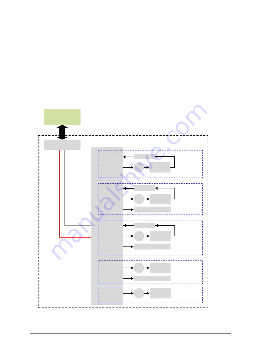
MRX-T4 control system block diagram is as shown in Figure 1-3.
MRX-T4 can be connected to a computer via USB, WiFi or LAN.
Users can control MRX-T4 through using MegaRobo Studio.
MRX-T4 consists of an MRH multi-function intelligent gateway module, which is connected to a MRQ-MV
stepper motor five-axis driver controller module via the CAN bus.
The five channels of the five-axis driver controller module control the corresponding five motors of the
base, big arm, small arm, wrist and end actuator.
MegaRobo Studio
Mot
or
Reducer
Angle sensor
Mot
or
Reducer
Angle sensor
Mot
or
Reducer
Angle sensor
Mot
or
Reducer
Base
Shoulder joint
Elbow joint
Wrist joint
End actuator
Channel 1
Channel 2
Channel 3
Channel 4
MRH
Computer
MRX-T4
Encoder
Encoder
USB/WiFi/LAN
CAN_H
CAN_L
Channel 5
Mot
or
Reducer
Encoder
Fiv
e
a
xis
d
riv
e
r c
o
n
tr
o
lle
r
Figure 1-3 MRX-T4 Control System Block Diagram


