


28
調節裝置
6. Adjustments
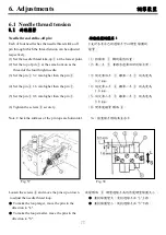
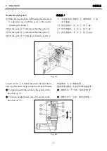
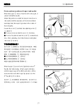
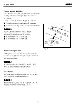
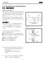
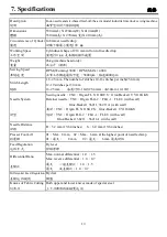
Front-and-rear position of looper and needle:
When the looper
①
moves from the left to the right, it
passes behind the needle.
Adjust the position to make the looper come close to
the needle with the clearance of 0 mm but without
touching when the looper tip comes at the center of
the left needle.
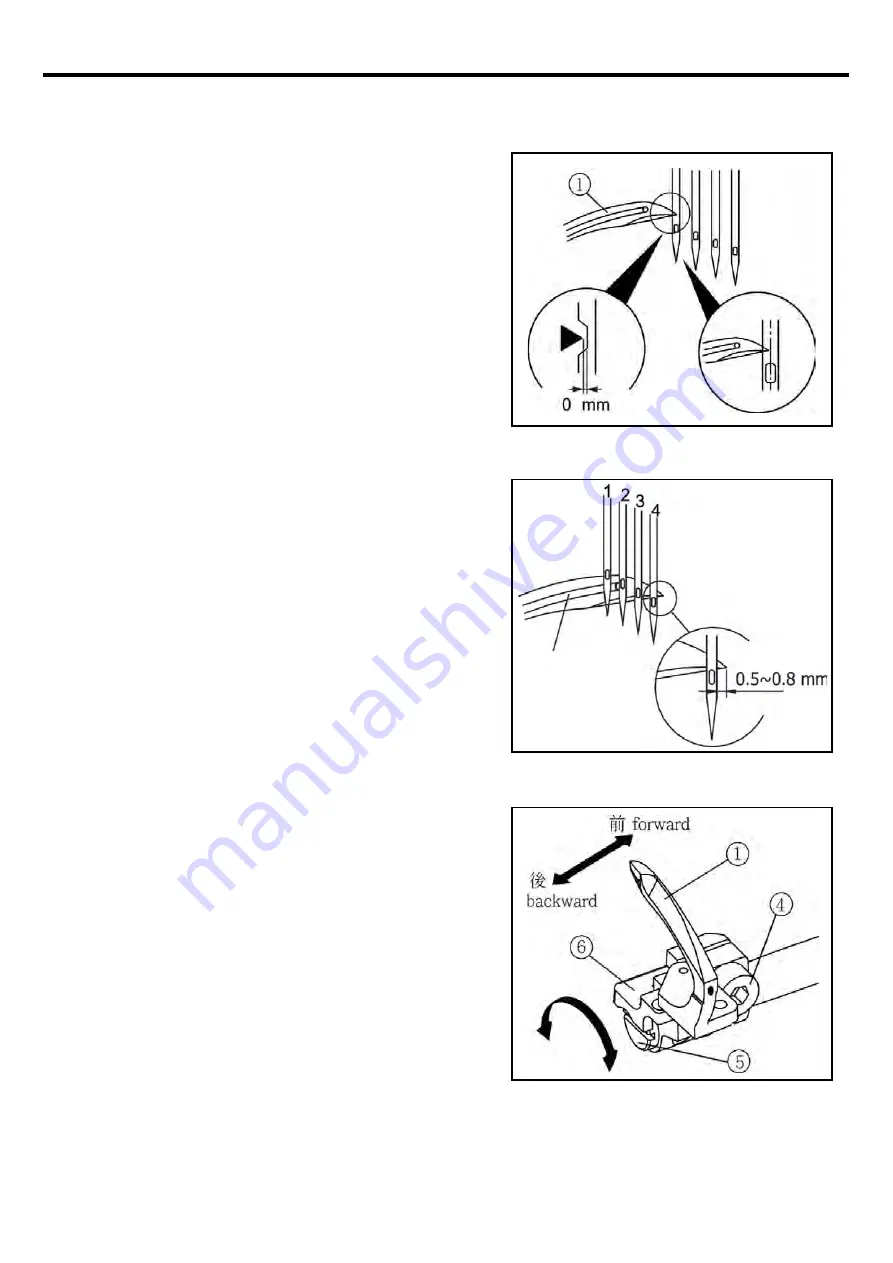
Loosen the screw
④
and turn the adjusting screw
⑤
to adjust it.
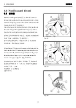
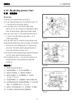
●
To move forward, turn the screw
⑤
clockwise.
●
To move backward, turn the screw
⑤
counterclock-
wise. After adjusting, check the distance and tighten
Fig. 49
the screw
④
securely.
下勾針的前後位置:
當下勾針
①
移動從左到右會在針的後面。調整
其位置使下勾針更接近針間隙 0 mm,但不能碰
到針,當下勾針的尖端在左針的中間時,放鬆
螺絲
④
轉動螺絲
⑤
調整前後位置。
● 順時間旋轉螺絲
⑤
會往前。
● 逆時間旋轉螺絲
⑤
會往後。
調整之後檢查間隙和鎖緊螺絲
④
。
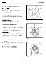
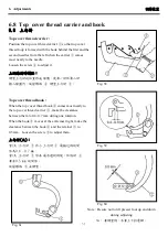
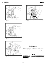
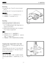
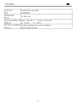
When Looper
①
moves to the right side to the 4
th
Fig. 50
Needle, the bottom edge of the Looper will align
with the upper edge of the 4th Needle hole. At this
moment, make sure the Looper tip passes over the
4
th
Needle by 0.5~0.8mm.
當勾針
①
往右移動至第四根針時,當勾針下沿
對齊針孔上沿時,勾針尖露出第四針 0.5~0.8mm。
Fig. 51
Summary of Contents for MJ101TX
Page 1: ......
Page 4: ...1 1 Name of each part Fig 1...
Page 5: ...2 2 Installation 2 1 Installation 2 1 2 1 1 Tabletop type 2 1 1 Fig 2...
Page 45: ......


