
5
2. Installation
安裝
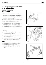
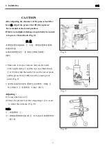
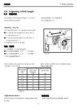
After adjusting the clearance of the presser bar lifter
lever
①
, adjust the presser foot lift when presser
bar is located at the lowest position.
If this is not adjusted, damage can probably be caused
to top cover thread hook. (Fig. 8)
在調整抬壓條連接軸
①
之後,調整抬壓腳在壓腳
的最低位置。
如果此項調整沒作,會導致上網線勾損壞。
Fig. 8
(
圖
8)
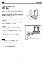
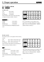
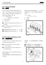
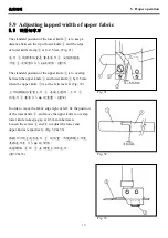
2. Make sure to keep a clearance between the notch
of the needle clamp
①
and the top cover thread hook
②
at 0.3mm when the needle bar is at the lowest point,
and the presser foot is fully raised by pressing foot
pedal. (Fig. 9)
2.當針柱在最低位置和壓腳完全抬舉時,針鎦
①
和上網線勾
②
需留間隙 0.3mm。
(
圖
9)
Fig. 9
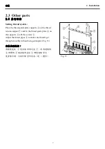
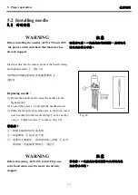
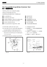
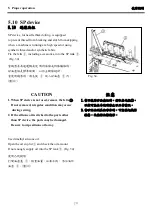
Adjusting :
(1) Loosen the lock nut
③
.
(2) Move the preseer foot lifter stop plunger
④
in or out
to adjust the clearance. (Fig. 10)
調整:
(1) 放鬆螺母
③
。
(2) 移動抬壓腳固定插銷
④
往內或往外來調整間隙。
(
圖
10)
Fig. 10
CAUTION
注意
Summary of Contents for MJ101TX
Page 1: ......
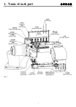
Page 4: ...1 1 Name of each part Fig 1...
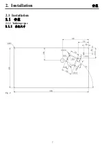
Page 5: ...2 2 Installation 2 1 Installation 2 1 2 1 1 Tabletop type 2 1 1 Fig 2...
Page 45: ......