www.megger.com/baker
Megger Baker ADX Quick Reference Guide
22
ADX Software Overview
Top Section—General Information
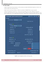
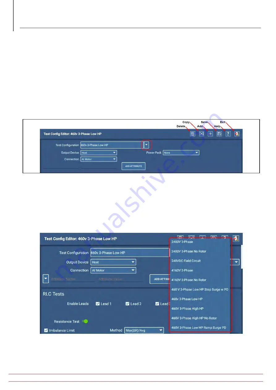
An icon toolbar appears at the top right of each screen to provide you with common functions as shown in the
example below. The icons and functions vary depending on the screen displayed. Hover the mouse cursor over an icon
(or press and hold icon when using the touch screen) to see flyout tooltips that identify the icon’s function.
The top section of the screen provides fields for locating and selecting a test configuration, specifying the device that
will perform testing on the Asset, the type of power pack used (if Output Device is Power Pack), and where the tester
will connect to the Asset.
When you click on the Connection drop-down list, select whether the ADX will be connected directly to the Asset (At
Motor) or to a remote testing junction (At Switchgear).
Define other general attributes for the Test Configuration by pressing the ADD ATTRIBUTE button.
Fig 19:
Test Configuration Editor; general information section.
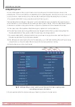
When the Test Configuration Editor opens and an Asset is not selected, it displays the first Test Configuration found
in the overall list. To change the view to another Test Configuration, click on the arrow to the right of the Test
Configuration field (as shown above) then select the configuration you want to view.
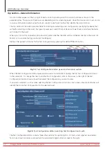
If an Asset is selected—such as when selecting the Test Configuration icon from a test screen—the screen title bar will
identify the Active Test Configuration for the selected Asset.
Fig 20:
Test Configuration Editor; selecting Test Configuration to edit.
The Test Configuration Editor contains three other sections for specifying RLC, DC tests, and Surge test parameters.
Tests in each section become active when the associated toggle button is moved to the right.


