ENERGIZED indicator flashes to alert you that voltage is being applied, along with the front panel LEDs.
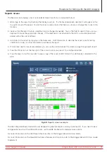
8. The voltage field (V at top left) displays the voltage level being applied as you turn and hold the ADX Voltage
Output Ramp switch clockwise.
9. When you reach the target voltage, release the Voltage Output Ramp switch and allow the tester to run for at least
10 pulses (indicated by Pulse Count in the display). Continue holding down the PPT button.
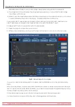
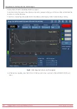
Pulse-to-pulse EAR+™ measurements are presented on the smaller graph on the bottom-left, while Line-to-Line
EAR+™ percentages are displayed in their respective fields to the right of the PPEAR+™ graph.
10. Release the PTT button to complete the test for the selected cable.
11. Repeat the process for all leads that you want to test.
12. When you have completed your testing, touch the Save icon then the Exit icon to return to the main screen.
Fig 51:
Manual Surge Test in progress.
If you want to collect Partial Discharge data for the device, slide the PD ENABLE switch to the right before testing
begins.
When conducting PD tests, inception values (PDIV and RPDIV) are captured as voltage is being increased to the target
level. To capture extinction values (RPDEV and PDEV), you will need to slowly decrease the applied voltage by turning
the ADX Voltage Output Ramp switch counter-clockwise.
PD threshold and event values are set in the Test Configuration selected for the Asset being tested.
For more information on Surge and PD testing, refer to the
Megger Baker ADX User Guide.
www.megger.com/baker
Megger Baker ADX Quick Reference Guide
50
Procedures for Testing with the ADX Analyzer


