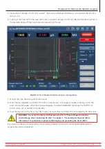
8. Test Lead 1 will be connected to motor lead 1, test lead 2 to the motor frame, and test lead three will be
disconnected (not contacting any motor lead or ground).
Fig 63:
Auto RLC Test; leads reconfiguring message for capacitance testing.
NOTE: Acknowledge this message only after the leads have been reconfigured.
Pressing the OK button will immediately initiate the capacitance test.
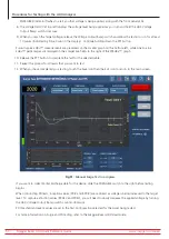
9. After the capacitance test completes, another message appears letting you know that the
capacitance test has completed and that you must restore the test leads to their original connections
before continuing on to DC Tests
.
CAUTION: Acknowledge this message only after the leads have been reconfigured. After pressing the
Continue Testing button, the software will immediately continue with the next test in the sequence—
often DC Tests.
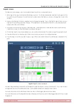
10. During sequenced DC testing, you can monitor test progress, viewing applied voltage along with current and
resistance values as they are collected. The software adds markers to key points in the test process where IR, DA, PI,
and HiPot testing completes. Testing begins immediately, and runs non-stop unless a failure is encountered.
NOTE: Use the E-STOP button on the lower right of the ADX front panel to stop the test and quickly de-
energize the high-voltage leads if needed.
Fig 64:
Auto DC Test screen—test in progress.
www.megger.com/baker
Megger Baker ADX Quick Reference Guide
61
Procedures for Testing with the ADX Analyzer


