background image

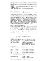
will not be activated when connected to

a diode. 
1.  Set the selector switch to Ω.

2.  Connect the test leads.
3.  The test will activate automatically.
4.  After the test probes are

disconnected, the

reading will be held for a few

seconds.

Zeroing of Test Lead Resistance
The resistance of the test leads can be

nulled on the continuity range (up to

9,99Ω). The null information is retained in non-volatile memory

and so will be remembered when the instrument is switched off.
1.  Select the Continuity range.

2.  Short the test leads across a known good conductor using 

prods.

3.  When the reading has stabilised, press the TEST button. 

A short ‘bleep’ will sound and the zero 

offset 

symbol will appear.

4.  To release the zero offset press the test button again.
Possible sources of error
Measurements and results can be effected by the following:

The impedance of operating circuits connected in parallel

Impedance such as inductors that vary during the 

measurement

A poor connection to the circuit under test.

Continuity Bleeper 
The continuity bleep     er sounds continuously when less than

5Ω is detected. Short bleeps will sound for resistances lower

than a few kΩ and above 5Ω. 
1.  Set the selector switch to 

2.  Connect the test leads.

Display:

Audible:

<5Ω

continuous bleep

<3kΩ

short bleep

>3kΩ

no bleep

Resistance Tests (kΩ)

This is a low voltage (5V) low current (25µA) test for sensitive

electronic equipment. It operates in the same way as the

continuity ranges. 

1.  Set the selector switch to kΩ.

2.  Connect the test leads.

3.  The test will activate automatically.

Voltage Tests (V)

If >1V a.c. or d.c. is present at the terminals the measured voltage

is indicated on the display. The voltage display will function within

FIG.1

Summary of Contents for BMM80 Series

Page 1: ...ve no broken or cracked insulation Ensure that hands remain behind guards of probes clips when testing U K Safety Authorities recommend the use of fused test leads when measuring voltage on high energ...

Page 2: ...he instrument enables the optional Megger SP6F Switched Probe to be used for two handed probe operation The 250V 500V and 1000V ranges can be used to test electrical installations in compliance with B...

Page 3: ...strument is switched to the OFF position when not in use Backlight The backlight is activated by pressing the key The backlight will remain illuminated for approximately one minute before automaticall...

Page 4: ...Testing and value assessment can be found in Megger Limited publications listed in the Accessories page Automatic Discharge When the TEST button is released after an insulation test or re pressed if...

Page 5: ...ossible sources of error Measurements and results can be effected by the following The impedance of operating circuits connected in parallel Impedance such as inductors that vary during the measuremen...

Page 6: ...F The measured capacitance is indicated on the display 1 Set the selector switch to uF 2 Connect the test leads 3 After a short settling time the reading will be displayed automatically Zeroing of uF...

Page 7: ...over Remove the cells if the instrument is not going to be used for an extended period of time Fuse Checking and Replacement To check the instrument fuse switch to an insulation range and press the TE...

Page 8: ...1999mV a c 16 460 Hz 5 5 digits d c milliVolts zeroing Up to 9 9mV Input resistance 3M CAPACITANCE Measuring Range 0 1nF to 9 99uF Accuracy 3 2digits 0 2nF uF zeroing up to 10nF Basic and service erro...

Page 9: ...00 4 76 0 50 0 44 10 00 9 56 0 60 0 54 20 00 18 8 0 70 0 63 30 00 28 4 0 80 0 73 40 00 38 0 0 90 0 82 50 00 47 6 1 00 0 92 100 00 92 0 SAFETY The instruments meet the requirements for double insulatio...

Page 10: ...erating humidity 90 RH at 40 C max Storage temperature range 25 to 65 C Calibration Temperature 20 C Maximum altitude 2000m Dust and water protection IP54 Temperature coefficient 0 1 per C WEIGHT 742g...

Page 11: ...contact Megger Limited or Megger Archcliffe Road Valley Forge Corporate Center Dover 2621 Van Buren Avenue Kent CT17 9EN Norristown PA 19403 England U S A Tel 44 0 1304 502243 Tel 1 610 676 8500 Fax 4...

Page 12: ...l U S A Fax 1 214 331 7399 Z A Du Buisson de la Couldre 23 rue Eug ne Henaff 78190 TRAPPES Tel 33 0 1 30 16 08 90 FRANCE Fax 33 0 1 34 61 23 77 This instrument is manufactured in the United Kingdom Th...

Reviews: