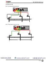
DET2/3
30
Test methods and set-up
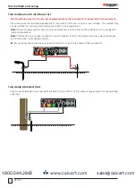
Two terminal earth resistance test
Warning: Make sure the circuit is de-energised, before the instrument is connected for measurement.
This will measure the resistance between the P1(X) and P2(Y) terminals using an ac test voltage. This method may
not be suitable for continuity and bonding tests (refer to local regulations).
Note:
The test voltage used for the two pole resistance test is ac and may not be suitable for all continuity tests
(see local regulations).
Note:
If the earth noise voltage is above 50 V peak to peak (18 Vrms), the display will show a warning triangle
and an excessive noise voltage indicator.
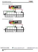
Set up the test leads and stakes as required (do not connect the test leads to the instrument):
P1 (E)
P2 (H)
C1
CA
T IV 300V
P1
P2
C2
E
ES
S
H
I
V
E
X
Y
V
MVC1010
MVC1010
MCC1010
I
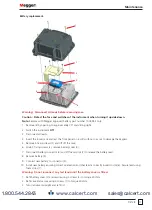
Two clamp (stakeless) test
The two clamp (stakeless) test uses both the MVC1010 and MCC1010 to obtain a measurement for the electrode
under test.
C1
CA
T IV 300V
P1
P2
C2
E
ES
S
H
I
V
E
X
Y
V
MVC1010
MVC1010
MCC1010
I
www.calcert.com
sales@calcert.com
1.800.544.2843
0
5
10
15
20
25
30

