Megger Limited
PWS / Nov 06
DET4TC/R Launch
24
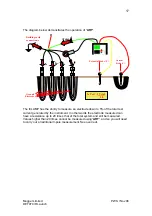
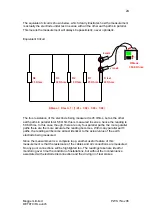
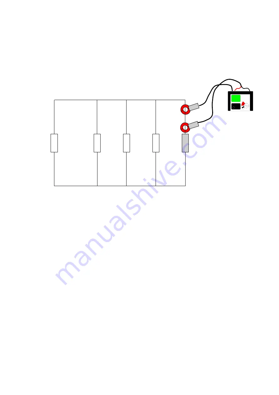
The equivalent circuit is shown below, which clearly illustrates how the measurement
is actually the electrode under test in series with all the other earth paths in parallel.
This means the measurement will always be pessimistic, never optimistic.
Equivalent Circuit
The true resistance of the electrode being measured is 45 Ohms, but as the other
earth paths in parallel total 5,6 Ohm this is measured in series, hence the reading is
50.6 Ohms. In this case, though, there are only four parallel paths, the more parallel
paths there are the more accurate the reading becomes. With many parallel earth
paths, the reading will become almost identical to the actual value of the earth
electrode being measured.
Since the measurement is a complete loop, another useful feature of this
measurement is that the resistance of the cables and all connections are measured.
So any poor connections will be highlighted too. The readings taken are ideal for
monitoring over time the condition of installations, but without the inconvenience
associated with electrode disconnection and the driving in of test stakes.
ICLAMP
VCLAMP
R test
R1
R2
R3
R4
25 Ohms
22 Ohms
19 Ohms
25 Ohms
45 Ohms
R Meas.
= 50.6 Ohms
R Meas. = R test + 1 / (1/R1 + 1/R2 + 1/R3 + 1/R4)


