16
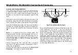
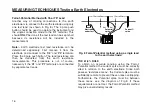
Fall-of-Potential Method with Short 'E' Lead
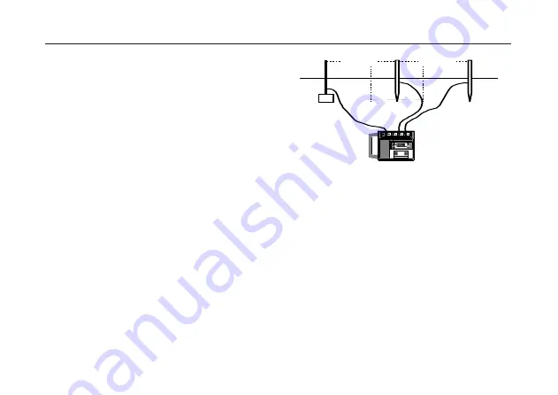
Another way of making connections to the earth
electrode is to connect to the earth electrode using only
one test lead (as shown in Fig. 8). The 3 pole push
button should be used to operate the instrument and
the single connection made to the ‘C1’ terminal. This
should ONLY be done if the test lead can be kept short
because its resistance will be included in the
measurement.
Note:- Earth electrode test lead resistance can be
determined separately. First remove it from the
electrode and connect to the 'C2' and 'P2' terminals.
Press the 3 pole push button. The lead resistance can
then be deducted from the earth resistance
measurements. This procedure is not, of course,
necessary if the 'C1' and 'P1' terminals are connected
by separate test leads.
Fig. 8 Fall-of-Potential method using a single lead
to the earth electrode.
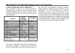
THE 61,8% RULE
To obtain an accurate reading using the Fall-of-
Potential method the current spike must be correctly
sited in relation to the earth electrode. Since both
possess ‘resistance areas’, the Current spike must be
sufficiently remote to prevent these areas overlapping.
Furthermore, the Potential spike must be between
these areas, see the diagram of Fig.9. If these
requirements are not met, the Fall-of-Potential method
may give unsatisfactory results.
MEASURING TECHNIQUES Testing Earth Electrodes
3m
3m
15m to 25m
15m to 25m
Electrode
under test
Potential
spike
Current
spike
k
C1
P2
C2
ES
H
4 POLE
3 POLE
MEASURE R
E
P1
ES
MEGGER
MEGGER
®
DET5/4D
DET5/4D
EARTH
EARTH
TESTER
TESTER
Summary of Contents for DET5/4D
Page 41: ...41...


