background image

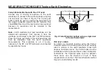
DETERMINING ‘STEP’ POTENTIAL

‘Step’ potential is the potential difference a person

would experience between his feet as he walked

across the ground in which a fault current was flowing.

Firmly connect the instrument as follows :-

1) Terminal 'C1' to the substation earth.

2) Terminal 'C2' to the Current spike inserted in the 

ground some distance away.

3) Firmly connect the 'P1' and 'P2' terminals to test 

spikes inserted in the ground 1 metre apart, (or the 

length of a step) at positions and respectively. 

is nearest to the substation earth. 

4) Press the 4 pole test push, and take a reading in 

the normal way.

Record the resistance indicated. This is the effective

resistance across the positions and B, as seen by

the test current.

The maximum value of the current that would flow in

the earth when a fault to earth occurred at the

substation must again be known. From Ohm's Law the

‘Step potential’ can be calculated.

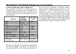
Fig.17 Determining ‘Step’ potential

24

MEASURING TECHNIQUES Testing Earth Electrodes

Earth

k

C1

P2

C2

E

S

H

4 P

O

LE

3 P

O

LE

M

EA

SU

RE

 R

E

P1

ES

M
E

G

G

E

R

M
E

G

G

E

R

®

 D

E

T

5

/4

D

D

E

T

5

/4

D

EA

RT

H

EA

RT

H

TE

ST

ER

TE

ST

ER

R

Current

spike

Earthed Perimeter Fence

1m

A

B

SUBSTATION

Summary of Contents for DET5/4D

Page 1: ...M DET5 4R DET5 4D Digital Earth Testers USER GUIDE GUIDE DE L UTILISATEUR GEBRAUCHSANLEITUNG GU A DEL USUARIO...

Page 2: ...er gloves and shoes should be worn The DET5 4D must be disconnected from any external circuit while its battery cells are changed Replacement fuses must be of the correct type and rating Before chargi...

Page 3: ...6 The Slope method 18 Method using Dead earth 21 BS7671 16th Edition IEE Wiring Regulations Requirements 22 Other methods 22 Determining Touch potential 23 Determining Step potential 24 Measuring soil...

Page 4: ...15 Test spike positions for BS7671 16th Edition IEE Wiring Regulations 22 Fig 16 Determining Touch potential 23 Fig 17 Determining Step potential 24 Fig 18 Soil resistivity measurement 26 Fig 19 Resi...

Page 5: ...tested The potential developed across the earth is compared with the current and after filtering and phase sensitive detection the resistance is given directly on the digital display Test frequency is...

Page 6: ...Wiring Regulations IEC 364 NFC 15 100 French Specification and VDE 0413 Part 7 1982 German specification The terminal C1 E is for the Current connection to the earth electrode to be tested The termin...

Page 7: ...a greater depth rather than increasing the cost by having to add further electrodes and associated cables in order to obtain a specified total earth system resistance EARTHING SYSTEMS MAINTENANCE Afte...

Page 8: ...terminal test To electrode under test 4 terminal test Battery compartment and charger socket cover DET5 4R Condition Warning l e d s 3 terminal push button Low Battery indicator point and k range indi...

Page 9: ...he earth electrode test spikes test leads or their terminations if any Live earths may be encountered It is recommended that they wear appropriate rubber gloves rubber soled shoes and stand on a rubbe...

Page 10: ...lly charged before embarking on a test sequence It can be extremely inconvenient if the battery becomes too low while a field test is in progress Similarly with the DET5 4D new batteries should always...

Page 11: ...anied by the warning alert indicator on the display This may be caused by an open circuit poor test lead connections or excessive resistance of the soil near the electrode under test and or the remote...

Page 12: ...id reading ensure that the P1 electrode is closer to C1 than the P2 electrode Fig 6 Reverse Polarity Indication SETTING UP THE TEST SPIKES ETC For earth electrode testing and for earth resistivity sur...

Page 13: ...he earth resistance and Current loop resistance If the Current spike resistance is too high for the required measurement range the instrument will autorange up to a lower current range which can toler...

Page 14: ...ld in place the protective panel covering the mains socket The supply voltage selection is by reversing the position of the fuse holder in the mains socket When the fuse and voltage selector are corre...

Page 15: ...ect of mutual inductance Firmly connect the C1 and the P1 instrument terminals to the earth electrode The diagram of Fig 7 shows the connections Operate the instrument as explained in the Basic Test P...

Page 16: ...nts This procedure is not of course necessary if the C1 and P1 terminals are connected by separate test leads Fig 8 Fall of Potential method using a single lead to the earth electrode THE 61 8 RULE To...

Page 17: ...of a single rod or plate etc and on medium systems with several rods The diagram of Fig 10 shows the connections for the 61 8 Rule Fig 10 The 61 8 Rule method For most purposes the Current spike shoul...

Page 18: ...sfactory and generally yields results of greater accuracy than those methods The equipment is set up as shown in Fig 11 The remote Current spike is placed 50 metres or more from the earth electrode sy...

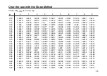
Page 19: ...R1 which is a measure of the change of slope of the earth resistance curve From the table on page 35 obtain the value of Pt Ec for this value of Pt is the distance to the Potential electrode at the po...

Page 20: ...ances chosen for EC in tests 1 and 2 were not large enough and that those chosen in tests 3 and 4 were preferable because they would give the more correct value of the earth resistance iii It is unrea...

Page 21: ...Using a shorting bar supplied short together terminals P2 and C2 2 Firmly connect a test lead to C1 and the other test lead to P2 and C2 3 Firmly connect the free ends of the test leads together as sh...

Page 22: ...5 then the current spike should be moved further away from the electrodes and the tests repeated Fig 15 Test spike positions for BS7671 testing Other Methods There are other methods of earth electrod...

Page 23: ...rimeter fence adjacent to the point where a person might stand 5 Press the 4 pole test push and take a reading in the normal way This is the effective resistance between the point of test on the fence...

Page 24: ...respectively A is nearest to the substation earth 4 Press the 4 pole test push and take a reading in the normal way Record the resistance indicated This is the effective resistance across the positio...

Page 25: ...of the soil resistivity of the surrounding site This will enable decisions to be made on the best position for the electrode s and to decide whether any advantage can be gained by driving rods to a gr...

Page 26: ...ne If both the spacing a and the depth a 20 are maintained a directly comparable reading will be obtained each time and thus regions of lowest resistivity can be located over a given area at the const...

Page 27: ...la 2 aR where R is the resistance measured in ohms a is the test spike spacing in metres and is the resistivity in ohm metres For non homogeneous soils the formula will give an apparent resistivity wh...

Page 28: ...t as low as possible 1 Using a shorting bar supplied short together terminals P2 and C2 2 Firmly connect a test lead to C1 and the other test lead to P2 and C2 3 Firmly connect the free ends of the te...

Page 29: ...ange The instrument measuring circuitry is connected to terminals P1 and P2 The voltage limiter and input buffer prevent damage to the instrument and loading of the resistance under test Synchronous f...

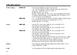
Page 30: ...1 mA a c r m s 2 k and 20 k ranges 100 A a c r m s Test current short circuit current is constant throughout a range Interference Interference voltages of 40 V pk to pk at 50 Hz 60 Hz 200 Hz or 162 3...

Page 31: ...the maximum error will not exceed 2 Max Output Voltage 50 V Display 31 2 digit l c d maximum reading 1999 Instrument Protection IP54 Temperature Effect 0 1 C over the temperature range 15 C to 55 C T...

Page 32: ...Internal 100 mA ceramic HBC 20 mm x 5 mm IEC 127 1 for current source protection Internal 100 mA ceramic HBC 20 mm x 5 mm IEC 127 1 for Potential circuit protection DET5 4R Internal 100 mA ceramic HBC...

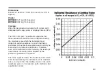
Page 33: ...m value which the instrument must indicate in certain conditions An earth test being performed on any electrode system would normally be carried out to a particular specification Therefore even at the...

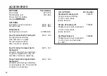
Page 34: ...Earth 6210 161 Testing kit Compact carrying bag containing 4 x push in spikes 3m 15m 30 and 50m of cable on cable tidy Three Terminal Compact Earth 6210 160 Testing Kit Compact carrying bag containin...

Page 35: ...8 0 6279 0 6277 0 6276 0 6274 0 51 0 6273 0 6271 0 627 0 6268 0 6267 0 6266 0 6264 0 6263 0 6261 0 626 0 52 0 6258 0 6257 0 6255 0 6254 0 6252 0 6251 0 6249 0 6248 0 6246 0 6245 0 53 0 6243 0 6242 0 6...

Page 36: ...0 5889 0 5887 0 5885 0 5883 0 5882 0 588 0 5878 0 5876 0 5875 0 76 0 5873 0 5871 0 587 0 5868 0 5866 0 5864 0 5863 0 5861 0 5859 0 5857 0 77 0 5856 0 5854 0 5852 0 585 0 5849 0 5847 0 5845 0 5843 0 58...

Page 37: ...386 0 5384 0 5382 0 538 0 5378 0 5375 1 02 0 5373 0 5371 0 5369 0 5367 0 5365 0 5362 0 536 0 5358 0 5356 0 5354 1 03 0 5352 0 5349 0 5347 0 5345 0 5343 0 5341 0 5338 0 5336 0 5334 0 5332 1 04 0 533 0...

Page 38: ...741 0 4738 0 4735 0 4732 0 4729 0 4726 0 4723 0 472 0 4717 1 28 0 4714 0 4711 0 4707 0 4704 0 4701 0 4698 0 4695 0 4692 0 4689 0 4686 1 29 0 4683 0 468 0 4677 0 4674 0 4671 0 4668 0 4664 0 4661 0 4658...

Page 39: ...3916 0 3912 0 3907 0 3902 0 3897 0 3893 1 50 0 3888 0 3883 0 3878 0 3874 0 3869 0 3864 0 3859 0 3855 0 385 0 3845 1 51 0 384 0 3835 0 383 0 3825 0 3821 0 3816 0 3811 0 3806 0 3801 0 3796 1 52 0 3791 0...

Page 40: ...Archcliffe Road Dover Kent CT17 9EN Tel 44 0 1304 502100 England Fax 44 0 1304 207342 or Megger Valley Forge Corporate Center 2621 Van Buren Avenue Norristown PA 19403 Tel 1 610 676 8500 U S A Fax 1...

Page 41: ...41...

Page 42: ...caoutchouc D brancher le DET5 4D d un circuit externe quel qu il soit pendant le rechargement des piles S assurer que les fusibles de rechange sont du type pr vu et ont un pouvoir de coupure correct A...

Page 43: ...ation secteur ou risque de le faire en pr sence d une anomalie 1 Toutes les personnes travaillant sur ce dispositif doivent avoir re u la formation n cessaire et doivent conna tre les proc dures d iso...

Page 44: ...ise l appareil DET5 4 s lectionne automatiquement la plage qui lui permet de tol rer cette r sistance plus lev e de la sonde de courant Cependant cela entra ne une perte de r solution 3 Si les conditi...

Page 45: ...dier avant que le r sultat fourni lors d un test puisse tre consid r comme valide Pour r soudre ce probl me il est possible de verser de l eau sur le sol proximit de la sonde de courant de d placer c...

Page 46: ...maintenant en ligne droite avant de recommencer ces essais Inversion de Polarite Lorsque les conducteurs de potentiel sont invers s par rapport aux conducteurs de courant l cran clignote entre les bar...

Page 47: ...ccepter la valeur affich e Cet instrument s lectionne automatiquement la plage de r sistances de mises la terre et la plage de r sistances de la boucle de courant Si la r sistance de la sonde de coura...

Page 48: ...t Pour ne pas risquer d endommager cette batterie il ne faut pas attendre qu elle soit compl tement plat Attention avant de recharger la batterie proc der aux v rifications suivantes Un fusible pouvoi...

Page 49: ...ger l instrument MISE EN PLACE OU REMPLACEMENT DE PILES DET5 4D Attention utiliser uniquement des piles de type correct piles alcalines CEI LR6 Attention avant de mettre en place ou de remplacer des p...

Page 50: ...Trousse d essai compacte de mise la terre quatre bornes 6210 161 Compose d un sac de transport contenant 4 sondes enfichables en acier galvanis de 10 mm de diam tre sur 450 mm de longueur quatre c bl...

Page 51: ...eparation d instruments ont t agr es pour faire des op rations de r paration sur la plupart des instruments Megger utilisant des pi ces d origine Megger Consultez le distributeur d sign agent officiel...

Page 52: ...ndschuhe und Gummischuhe getragen werden Beim Aufladen der Batteriezellen mu das DET5 4D von externen Stromkreisen getrennt sein Es m ssen Ersatzsicherungen der richtigen Nennleistung installiert werd...

Page 53: ...Me leitungen oder deren Abschlu widerst nde nicht zu ber hren wenn irgendwelche spannungsf hrenden Erdungsleitungen auftreten sollten Es wird empfohlen die entsprechenden Gummihandschuhe und Schuhe mi...

Page 54: ...fung zufriedenstellend sind stabilisiert sich die Leuchtanzeige und die angezeigten Werte k nnen akzeptiert werden 4 Es empfiehlt sich beim Arbeiten mit dem DET5 4R vor Beginn einer Pr fsequenz darau...

Page 55: ...r fstab f r Hochspannungswiderstand Rp Um anzuzeigen da der Widerstand des Stromkreises zu hoch f r eine genaue Messung ist leuchtet automatisch die Rp Leuchtanzeige zusammen mit der Warnanzeige der B...

Page 56: ...ein g ltiges Ergebnis erzielen zu k nnen mu darauf geachtet werden da sich die P1 Elektrode n her bei der C1 als bei der P2 Elektrode befindet Fig 5 Anzeige f r Polarit tsumkehrung Einrchtung Der Pr...

Page 57: ...chten mu die Ursache f r den jeweiligen Umstand beseitigt werden bevor der angezeigte Wert akzeptiert werden kann Das Instrument reagiert automatisch sowohl auf den Erdungs als auch auf den Stromschle...

Page 58: ...r die Batteriekapazit t auf der Bildanzeige erscheint Falls die Bildanzeige beim Betrieb des Instruments leer bleibt k nnte dies daran liegen da die Batterie vollkommen ersch pft ist Bitte vermeiden...

Page 59: ...er ein EINSETZEN ODER AUSWECHSELN DER BATTERIEN DET5 4D Achtung Verwenden Sie nur Batterien des richtigen Typs Alkali IEC LR6 Vorsicht W hrend des Einsetzens oder Auswechselns von Batterien sollten ke...

Page 60: ...bidungskabel auf Aufwickelvorrichtungen Kompakter Erdungspr fkasten mit 4 Anschl ssen 6210 161 bestehend aus einer Tragetasche inklusive 4 versenkbare Pr fstabe aus galvanisiertem Stahl 10 mm Durchmes...

Page 61: ...Road Dover Kent CT17 9EN Tel 44 0 1304 502243 England Fax 44 0 1304 207342 oder Megger Valley Forge Corporate Center 2621 Van Buren Avenue Norristown PA 19403 Tel 1 610 676 8500 U S A Fax 1 215 676 8...

Page 62: ...cho Siempre que vaya a sustituir las pilas del probador DET5 4D primero descon ctelo del circuito externo Los fusibles de recambio deben ser del mismo tipo y amperaje Cuando vaya a cambiar la pila del...

Page 63: ...imientos de aislamiento y de seguridad del sistema en que est n trabajando Estas personas deben tener en claro que donde exista la posibilidad de encontrar instalaciones de tierra bajo tensi n no se d...

Page 64: ...falsas Nota si la resistencia de la pica de corriente es demasiado alta para el rango de medici n requerido el probador DET5 4 selecciona autom ticamente un rango que pueda tolerar una mayor resistenc...

Page 65: ...talla La causa de esta condici n puede ser un circuito abierto una conexi n mala entre los cables de prueba o la resistencia excesiva en el rea cercana al electrodo bajo prueba o en la pica de corrien...

Page 66: ...de tal forma que queden en ngulo recto con respecto a su primera posici n y en l nea recta Una vez corregido el problema vuelva a ejecutar la prueba POLARIDAD INVERTIDA Si la polaridad de los cables...

Page 67: ...que si se indica una condici n adversa sta debe corregirse para que la lectura sea v lida El instrumento determina autom ticamente los rangos de la resistencia de tierra y la del ciclo de corriente Si...

Page 68: ...aparezca el s mbolo que denota una condici n de carga baja Si la pantalla del instrumento queda en blanco mientras est en funcionamiento la causa m s probable es una condici n de descarga total de la...

Page 69: ...imentaci n del instrumento INSTALACI N O REEMPLAZO DE LAS PILAS DET5 3D Precauci n Utilice nicamente pilas alcalinas IEC LR6 Precauci n Antes de instalar o sustituir las pilas aseg rese de que todas l...

Page 70: ...ompacto de la prueba de tierra de 4 terminales Bolsa que contiene 4 picas de hincadura de acero galvanizado de 10 mm de di metro x 450 mm de longitud cables de 3 15 30 y 50 m con terminaci n en forma...

Page 71: ...avor con Megger Limited Archcliffe Road Dover Kent CT17 9EN Tel 44 0 1304 502243 England Fax 44 0 1304 207342 o Megger Valley Forge Corporate Center 2621 Van Buren Avenue Norristown PA 19403 Tel 1 610...

Page 72: ...APPES France T 33 0 1 30 16 08 90 F 33 0 1 34 61 23 77 OTHER TECHNICAL SALES OFFICES Toronto CANADA Sydney AUSTRALIA Madrid SPAIN Mumbai INDIA and the Kingdom of BAHRAIN Megger products are distribute...

Reviews: