Insulation Testing
1.
Turn the instrument ‘On‘ by selecting the M
Ω
range.
2.
Connect the test probes to the isolated circuit under test.
3.
Press and hold the push button; the display shows the insulation value.The
reading will remain displayed for a few seconds after the push button is
released. As an additional safety feature, instruments with 1000V range will
flash
symbol before performing a test.
4.
Release the push button before removing the test leads (to enable the
instrument to discharge the circuit under test).
5.
On completion switch to the ‘OFF’ position. Alternatively auto shut off
operates after 12 minutes of inactivity.
SPECIFICATION
Insulation
Test Voltage Accuracy:
-0% + 30% (over full operating temperature)
into 0 to 1mA load
Measuring Range:
0,01M
Ω
- 999M
Ω
(Digital)
0,1M
Ω
-
∞
(Analogue)
Short Cct. Current:
Less than 2mA
Accuracy (at 20°C):
± 3% ±2 digits up to 10M
Ω
± 5% ±2 digits up to 100M
Ω
± 30% up to 999M
Ω
Output Noise Voltage:
Typically 2V pk to pk at 20kHz (at 1mA load)
Hum Rejection:
<10% error with 100µA RMS (0,2M
Ω
to
∞
)
Continuity
Measuring Range:
0,01
Ω
- 99,9
Ω
Open Cct. Voltage:
5V ±1V
Accuracy (at 20°C):
0,01
Ω
- 9,99
Ω
±3% ± 2 digits (
I
SC
>200mA)
10
Ω −
100
Ω
± 5% ± 2 digits (
I
SC
>20mA)
Lead res. comp:
0 to 9,99
Ω
Hum Rejection:
<3% error with 1V RMS (0,2
Ω
to 50
Ω
)
Continuity Beeper:
On
position, the beeper sounds at <5
Ω
resistance
Environmental Conditions
Temperature Coefficient: <0,1% per °C
Temperature Range:
Operating: -20°C to +40°C (full measurement range)
-20°C to +60°C (to 100 M
Ω
maximum)
Storage:
-25°C to +65°C
Humidity:
90% RH at 40°C max
General Specifications
Display:
3 digit L.C.D. Maximum reading 999
Auto Shut off:
Operates after 5 minutes of inactivity by the
instrument in Continuity position and 12 minutes in Insulation position. Beep
notes pre-empt auto shut off. The instrument can be switched back on by
pressing the test button, or by selecting ‘OFF‘ and then the required position.
Default Live Circuit Warning
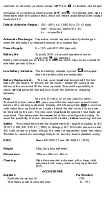
When more than 25 V is applied to the terminals, the instruments default to a
1000V
100
200
300
400
500
600
700
800
900
1000
1100
1200
1300
0,01M
Ω
0,1M
Ω
1,0M
Ω
10M
Ω
100M
Ω
Load
Terminal Voltage
1000 V Range
500 V Range
0.5M
Ω
250 V Range
0,2M
Ω
0,5M
Ω
1M
Ω
2M
Ω
5M
Ω
0,2M
Ω
0,5M
Ω
1M
Ω
2M
Ω
5M
Ω
10M
Ω
Minimum Indicated Value
Terminal Characteristics
Limiting Value


