M
AVTM651070 Rev B Nov 2006
16
Inductive Connection
This method is convenient because it does not require interruption of service.
No test leads are needed. When the cable or pipe has no insulation or
nonconductive coating, the operating range will be very short.
Place the transmitter on the ground as close as possible to the path of the cable
or pipe. Align the arrows on the transmitter control panel at a small angle to the
cable or pipe. Set the FREQUENCY switch to RF. When you turn the
transmitter on, the LOADING indicator will start blinking. First locate the broad
transmitter null then, move toward the expected cable path while looking for the
signal carried by the cable.
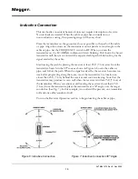
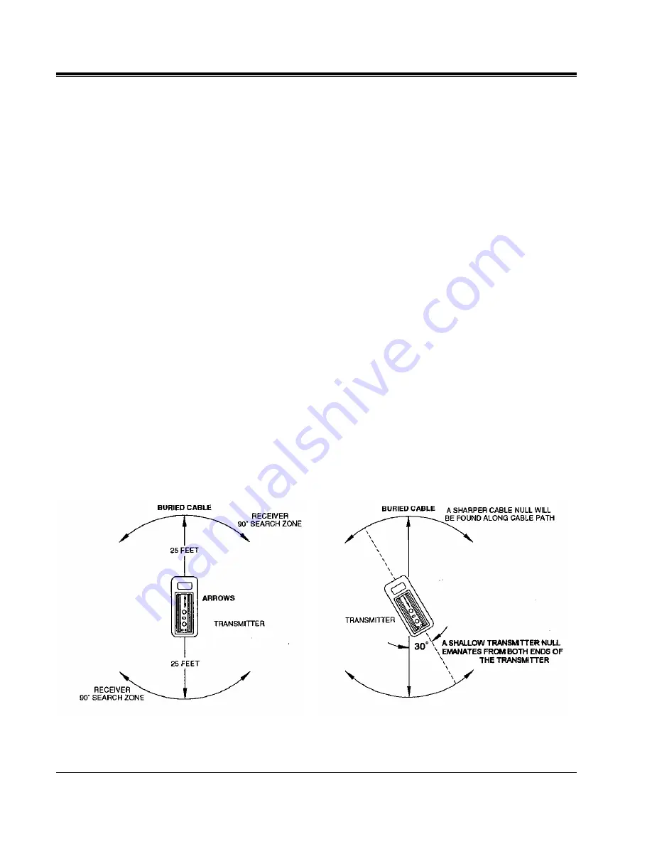
Start tracing the path by placing the receiver at least 25 ft (7.6 m) away from the
transmitter. Search in the 90
°
zone as shown in Figure 6. Locate the cable or
pipe, and follow the path. When the signal received by the receiver becomes too
weak after progressing along the route, move the transmitter to a location no
closer than 25 ft (7.6 m) behind the receiver and continue tracing. Note that the
transmitter may produce its own null when the receiver is within 25 ft (7.6 m) of
the transmitter. When you cannot avoid locating the receiver closer than 25 ft
(7.6 m) from the transmitter, place the transmitter at a 30° angle over the target
conductor. (See Fig. 7). In this example, two nulls will be present, one transmitter
null and one cable/conductor null.
Turn to the Receiver Operation section to begin locating the cable or pipe.
Figure 6: Inductive Connection
Figure 7: Inductive Connection 30
°
Angle
Summary of Contents for L1070
Page 2: ...L1070 and L1071 Portable Locator Instruction Manual...
Page 4: ......
Page 8: ...AVTM651070 Rev B Nov 2006 iv M...

