TRANSMITTER OPERATION
AVTM651070 Rev B Nov 2006
19
Telephone Direct Shield Connection
We recommend this method for telephone service because there is usually a
ground lug available for making connections, and damage to the cable is unlikely.
This method provides reliability, and you do not have to interrupt service.
However, all connections must be made by either an authorized telephone
company employee or an authorized locator contractor. Readings may be
confusing if several cable shields are bonded together.
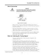
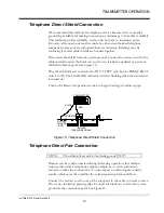
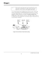
Disconnect the shield from the system ground. Connect the red test cord to the
cable shield. Connect the black test cord to the telephone pedestal or previous
shield attachment point. See Figure 10.
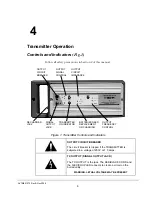
Plug the red/black test cord into the TX OUTPUT jack. Set the FREQUENCY
switch to AF. The LOADING indicator will start blinking when the transmitter
is turned on.
Turn to the Receiver Operation section to begin locating the cable or pipe.
Figure 10: Telephone Direct Shield Connection
Telephone Direct Pair Connection
NOTE:
This method will not work with a floating ground ESS #5.
Because service is disconnected during the tracing operation, this method
requires that either a telephone company employee or other authorized
contractor make the connections. You can expect to obtain highest quality
results, which more than justifies the extra preparation time and effort.
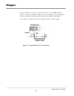
Connect the red test cord to one of the wire pairs in the cable you want to trace.
Do not use insulation piercing clips. Connect the black test cord to the system
ground at any convenient point. See Figure 11.
TRANSMITTER
BLACK
BURIED
RED
PEDESTAL
TELEPHONE CABLE
RYCOM
GROUND
ROD
Summary of Contents for L1070
Page 2: ...L1070 and L1071 Portable Locator Instruction Manual...
Page 4: ......
Page 8: ...AVTM651070 Rev B Nov 2006 iv M...

