M
AVTM651070 Rev B Nov 2006
34
NOTE
:
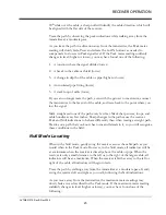
The bars may not always flash at the center of the graph. In this case the
faults location is determined by the immediate change in fault direction
when the G
ROUND
R
ETURN
P
ROBE
is move slightly in either direction.
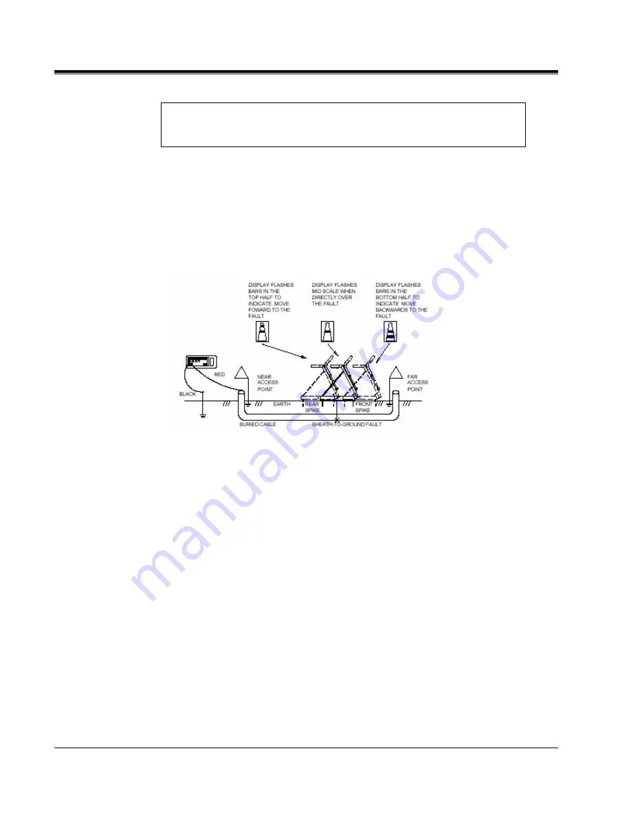
As you walk the path using the GRP, drop the probe every three or four steps.
Once the signal indicator on the RECEIVER changes directions, you should
move back taking smaller steps, covering smaller segments of ground to avoid
passing the fault. The fault lies in the center of the GROUND RETURN
PROBE spikes. Finally change the orientation of the GRP 90 degrees and move
the GRP both forward and backward, re-centering the graph. This will ensure an
accurate location of the fault.
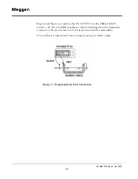
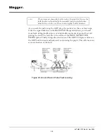
Figure 20: Ground Return Probe Fault Locating
Summary of Contents for L1070
Page 2: ...L1070 and L1071 Portable Locator Instruction Manual...
Page 4: ......
Page 8: ...AVTM651070 Rev B Nov 2006 iv M...

