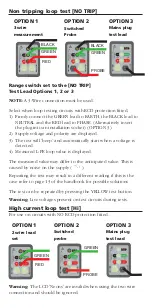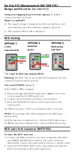
No Trip PFC Measurement (NO TRIP PFC)
Range switch set to [
NO TRIP PFC
]
Using non tripping loop test lead options 1, 2 or 3 -
connect the leads as shown.
Phase to earth PFC
1) The supply voltage is displayed and the test will beep, and
automatically start when sufficient voltage is detected.
2) The measured PFC result is displayed.
RCD testing
1/2
I, I and 5I RCD trip timing [RCD]
Warning:
The LCD 'Neons' are invalid when using the two wire
connection and should be ignored.
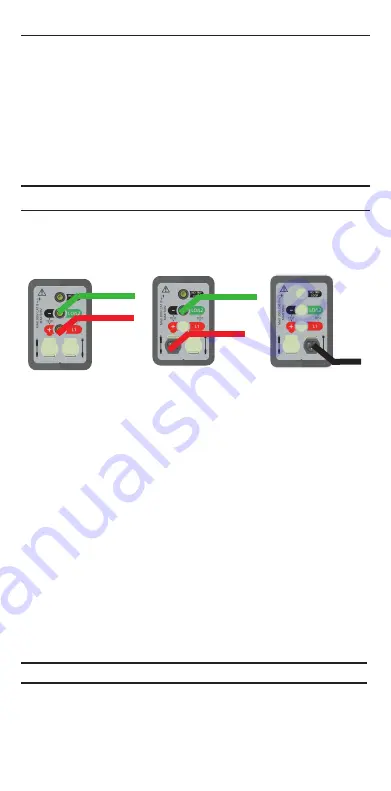
Test Lead OPTION 1,2 or 3
Select
1/2
I
,
I
or
5I
as required.
1) Ensure the right hand RCD range switch [
mA
] is set to the
correct range for the RCD under test.
2) Connect the test leads to the RCD as shown above.
3) Press the YELLOW test button on the instrument or the
switch probe.
On
1/2
I
the message >1999 ms is displayed after 2 seconds.
NOTE:
The message ‘TrP’ will be displayed if the RCD trips
unexpectedly.
On
I
the trip time is displayed (or >400 ms if RCD fails to trip).
On
5I
the trip time is displayed (or >40 ms if RCD fails to trip).
RCD auto test sequence (MFT1552)
To start the RCD auto test
1) Connect the RED test lead to the “Live” temminal of the RCD
and GREEN and BLACK test leads to the earth conductor.
Alternatively connect the mains plug test lead to a supply outlet.
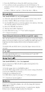
2. Select the AUTO RCD TEST on the main range knob and the
RCD current rating on the small range knob.
OPTION 1
2 wire
measurement
OPTION 3
Mains plug
test lead
OPTION 2
Switched
probe
GREEN
GREEN
RED
PROBE


