display indicates the actual test current (e.g. 205 mA. The
maximum is defined in setup menu.
Note: The test current displayed is the actual test current used
during the test, which will depend on the resistance of the circuit
under test.
Resistance measurements (k
Ω
Range)
1. Turn the instrument ‘ON’ by rotating the selector switch to the
desired [k
Ω
] position.
2. Connect the test leads to the isolated conductors under test.
3. Observe the test result, displayed automatically.
Setup options
The setup position permits the user to adjust various threshold
values and default settings. When SETUP is selected, the instrument
firmware revision is displayed, followed by the buzzer alarm
threshold.
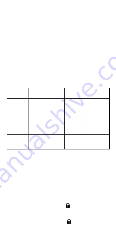
Displayed Meaning
symbol
Default
setting
Setting
options
BUZ
Set top threshold for
continuity buzzer in
ohms.
2
Ω
1, 2, 5, 10, 20
Buzzer sounds if
result is less than set
value.
Ω
Loc
Lock button ON/OFF
ON
ON / OFF
ISC
Setup maximum
continuity short-circuit
current.
200 mA
20 mA, 200 mA
(default 200 mA)
Setup procedure
1. Turn the instrument ‘ON’ by rotating the selector switch to the
Setup position. The firmware version is displayed prior to the first
setting BUZ.
2. Press the TEST button repeatedly to select the desired parameter,
BUZ, Loc, ISC etc.
3. When the function to be changed is displayed,
press and
hold
the TEST button to change the value. Each subsequent
press increments the limit. Holding down the TEST button will
automatically increment.
4. Changing a value will start the lock [
] symbol flashing. This
indicates a value has been changed
but not saved.
5. Save new limit by pressing the Lock [
] button. Saved changed


