background image

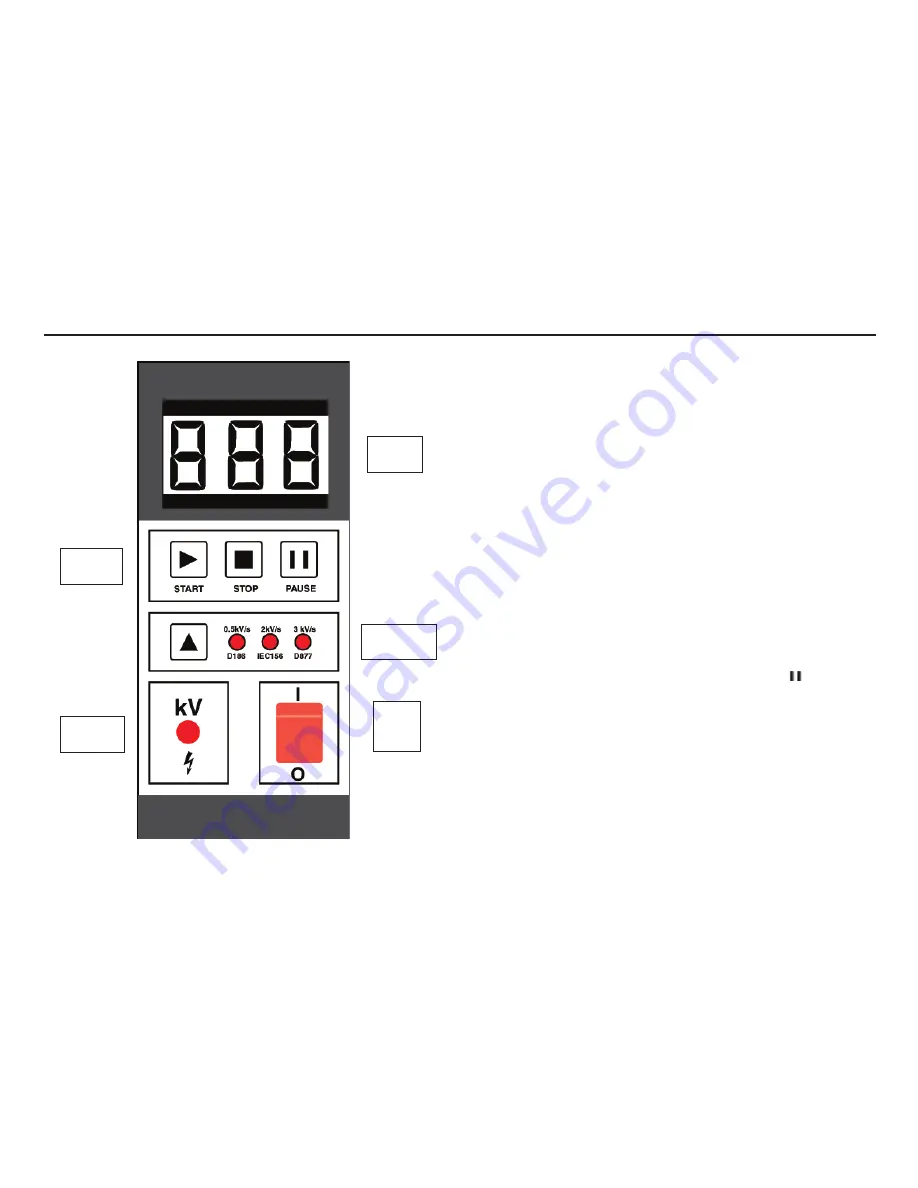
Control Panel

The control panel contains the supply on/off switch, the high voltage display, voltage 
ramp rate selection and the three control keys. The operation of the instrument is 
very simple. When the instrument is turned on, the on/off switch is illuminated, and 
the software edition code will be flashed up on the display. 

Breakdown Testing

The suitable ramp rate for the test to be performed should be selected using the ‘

s

’ 

key. The 

START

 key ‘     ‘ will then turn on the high voltage. The red H.V. indicator 

will light to show the output voltage is on. The voltage will then increase at the 
selected ramp rate and the corresponding value will be shown on the display. If oil 
breakdown occurs the instrument will detect this and immediately shut off the high 
voltage. The breakdown voltage value will be left on the display until the next test is 
started. If no breakdown occurs, the high voltage will rise to  
60 kV. At this point the test voltage is cut off and this maximum value left on the 
display.

A test can be stopped at any time by pressing the 

STOP

 ‘

’ button. This will remove 

the high voltage from the oil sample and leave the display at 

0,0 kV

.

Withstand Testing

A Withstand (proof) test can be carried out by pressing the 

PAUSE

 ‘     ‘ key. This will 

maintain the high voltage at the current value for one minute. After this time the 
high voltage will continue to rise until one of the following:-

1) Oil breakdown occurs

2) The 

STOP

 ‘

’ key is pressed 

3) The output voltage reaches the maximum value of the test set. 

During withstand testing the ramp rate can be changed while the pause is in 
progress. This can allow the withstand test value to be accurately set by adjusting the 
ramp rate to the lowest value.

6.

Mains 
on/off 
switch

HV on 
indicator

Ramp rate 
selection

Main 

controls

LED 
Display

Control Panel

s

Summary of Contents for OTS60SX/2

Page 1: ...M OTS60SX 2 Semi Automatic Oil Test Set User Guide...

Page 2: ...ampling 5 Preparing the Oil Test Vessel 5 Control Panel 6 Breakdown Testing 6 Withstand Testing 6 Warning messages 7 Testing to National Standards 7 Sampling and Testing Oil for Dielectric strength 8...

Page 3: ...sting Replacement fuses must be of the correct type and rating NOTE THE TEST SET MUST ONLY BE USED BY SUITABLY TRAINED AND COMPETENT PERSONS TO PREVENT DAMAGE DO NOT TRANSPORT INSTRUMENT WITH TEST CEL...

Page 4: ...sted according to breakdown specification by using a suitable sequence of tests The instrument is constructed in a strong sheet steel case Handles are provided for ease of transportation A pouch is lo...

Page 5: ...f the oil may lead to misleading results Always run off a small amount of oil before sampling and ensure that the flow of oil is steady Preparing the Oil Test Vessel Optional vessels are available for...

Page 6: ...left on the display until the next test is started If no breakdown occurs the high voltage will rise to 60 kV At this point the test voltage is cut off and this maximum value left on the display A tes...

Page 7: ...60SX 2 Oil Test Set The test vessel must be kept scrupulously clean Before each use dismantle the test vessel clean and dry re assemble and set the electrode gap to 2 54 mm 0 100 inch Dismantling the...

Page 8: ...l and the sampling apparatus as the condition of the oil itself After cleaning the apparatus it should under no circumstances be wiped dried or even handled with a dusty or fibrous cloth as loose dust...

Page 9: ...revent contamination is necessary when a test is to be made on a bulk delivery tanker and on all occasions when a high value of dielectric strength is anticipated The procedure suggested above should...

Page 10: ...3 min 3 min 5 min 5 min 3 min 3 min 3 min 3 min 3 min 3 min 3 min 3 min 10 min 3 min Rate of rise of voltage 2 kV s 3 kV s 0 5 kV s 0 5 kV s 2 kV s 2 kV s 2 kV s 2 kV s 2 kV s 2 kV s 2 kV s 3 kV s 3...

Page 11: ...n with automatic 1 minute timer for Withstand testing Display 0 0 60 0 kV LED digital display HV on LED Ramp rate LED Measurement Accuracy 2 3 digits Controls Start Pause Stop Ramp Rate select and Pow...

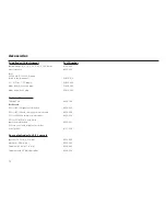
Page 12: ...Accessories Carrying Case 6420 106 Test Vessels 0 5 l for IEC156 spherical electrodes 6320 233 0 5 l for IEC156 with stirrer spherical electrodes 6320 236 0 5 l for VDE0370 mushroom electrodes 6320 2...

Page 13: ...contact Megger LImited or Megger Archcliffe Road Valley Forge Corporate Center Dover 2621 Van Buren Avenue Kent CT17 9EN Norristown PA 19403 England U S A Tel 44 0 1304 502243 Tel 1 610 676 8579 Fax...

Page 14: ...333 3201 T 33 1 30 16 08 90 F 1 214 331 7399 F 33 1 34 61 23 77 OTHER TECHNICAL SALES OFFICES Toronto CANADA Sydney AUSTRALIA Madrid SPAIN Mumbai INDIA and the Kingdom of BAHRAIN Megger products are...

Reviews: