Preliminary Procedure
1. Isolate the protection equipment to be tested. Ensure that the test set is disconnected from the mains
supply before making (or breaking) connections.
2. Connect the test cables to the test set and to the equipment under test. For current injection and IDMT
relay testing connect heavy current test cables to the wing-nut current terminals. For auxiliary voltage
testing connect 2 A rated test leads to the voltage terminals.
3. When using the time counter facility, connect the protective relay contacts to the ‘TIMER STOP’
terminals.
4. Set the ‘RANGE’ switch to the required output range.
5. Open the lid of the controller to gain access to the display and key-pad.
Note:-
If desired, lift the controller from its fixing on the main unit.
6. Switch the mains power supply on and switch the test set’s ‘POWER’ switch to ‘I’ (i.e. on).
7. The display screen will show a copyright message briefly, followed immediately by the message
‘SYSTEM RESETTING PLEASE WAIT’ which also appears only briefly. (‘SYSTEM RESETTING’
flashes on and off to give the message more emphasis).
Note:-
This message occurs frequently during the testing procedure but remains only for a short time
while the variac returns to zero and the circuit makes itself ready to continue.
When the test set is switched on the variac is wound through a full turn by the stepper motor to
clean away any dust or dirt that may have settled on the track and which may cause a
discontinuity. During this operation the solid state relay is turned off so that no output should
appear at the terminals. If this is not the case the circuit will detect an output voltage; the
variac will be wound back to zero and the display screen will indicate a relay fault.
After the variac has reset normally the main menu will be displayed on the screen.
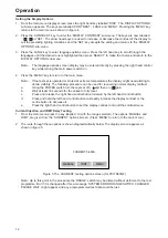
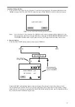
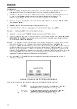
8. The main menu showing the testing options then appears on the display screen as in figure 4.
The options given and allocated to the three keys below the display are:-
A
0-600 A
the display shows the maximum current of the range
(0-300 A)
selected by the ‘RANGE’ switch.
V
0-125 V
the display shows the maximum voltage of the range
(0-250 V)
selected by the ‘RANGE’ switch.
DISP
the option used to set the display requirements.
11
0-600A
A
0-125V
V
DISP
SELECT OPTION
Figure 4 The main menu (for PCITS600/2) showing the testing option available
Summary of Contents for PCITS2000/2
Page 1: ...M PCITS600 2 PCITS2000 2 Primary Current Injection Test Sets User Guide Benutzerhandbuch...
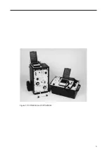
Page 5: ...5 Figure 1 PCITS600 2 and PCITS2000 2...
Page 23: ...23...
Page 37: ...37...
Page 38: ...38...

