Applications
The main application of these Primary Current Injection Test Sets is the testing of complete electrical
distribution/supply relay protection systems. They are normally employed at the time of commissioning
protection equipment or after major repair since it is usually inconvenient to take the complete system “off
line”. All components of the protection system are tested i.e. the isolated high voltage conductor, the current
transformer, the protection relay and the circuit breaker.
Most electricity supply protective equipment is fed from a current transformer on the supply cable or bus
bar. A high test current, sufficient to cause the protection equipment to operate, is injected into the supply
cable and the time taken for the protecting relay to operate is then measured.
Primary testing will detect current transformers connected with incorrect polarity or relays that have been
set in the wrong sequence in differential systems. However the inconvenience of breaking the primary
circuit means that the method is unsuitable for routine testing.
For routine testing secondary current injection testing is usually employed. This checks the operation of the
protecting relay etc. but does not test the overall system including the current transformer.
Primary testing usually requires a high current (over 500 A). Secondary current injection testing is easier
since there is not the need to break the primary circuit and the current required through the operating coil of
the protective device is lower (up to 100 A).
The relay incorporated in systems usually has a critical performance in relation to time. The built-in timer
will enable the operating time of the relay to be thoroughly tested.
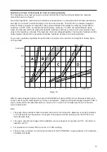
Several methods of measuring the operating time are possible. Figure 2 illustrates two methods when the
test current is not interrupted by the relay operating. Condition A tests the relay by sensing the relay
changing state with the timer stop terminals. Note: the relay contacts are connected directly across the
TIMER-STOP terminals. Similarly, condition B tests the relay and the circuit breaker trip coil by monitoring
auxiliary contacts. Figure 3 shows the PCITS measuring the total trip time by sensing the interruption of
current flow in the circuit under test.
A further application of these test sets is the testing of the current transformer’s phasing. Again the test is
normally performed at the commissioning stage or after major repair.
The auxiliary voltage outputs may be used for testing voltage operated relay coils or checking the
magnetization characteristics of current transformers.
Applications
7
–
+
X
PCITS
PROTECTIVE
RELAY
Condition A
Condition B
Aux
Contact
–
+
X
PCITS
PROTECTIVE
RELAY
Condition C
Closed
Figure 2
Figure 3
Summary of Contents for PCITS2000/2
Page 1: ...M PCITS600 2 PCITS2000 2 Primary Current Injection Test Sets User Guide Benutzerhandbuch...
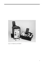
Page 5: ...5 Figure 1 PCITS600 2 and PCITS2000 2...
Page 23: ...23...
Page 37: ...37...
Page 38: ...38...

