LED indicators
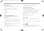
Three RED led indicators show circuit connection status when correctly
connected to a live circuit. These are for indication purposes only and
should not be relied upon as a indication of the presence of a hazardous
voltage.
When connected to the circuit to be tested the three status LED’s will
show the following supply connection information:
LED Normal
Reversed
Notes
Indicator Supply
(L-N) supply
=ON = OFF
L - PE
Voltage between L- PE
greater than 25 V
L - N
Voltage between L-N
greater than 25 V
N - PE
Voltage between N-PE
greater than 25 V
Warning:
Voltage indicator LED’s cannot reveal a N-PE supply reversal
Polarity Indication
If connected to a single phase power supply by a plug or by the 3-wire
lead set, three LED’s marked L-PE, N-PE and L-N respectively will
indicate supply polarity
NOTE:
The presence of a voltage between phase and earth does not
prove earth continuity, as the earth could have a high resistance and a
voltage would still be measured. To test earth continuity refers to the
sections on loop testing.
RESIDUAL CURRENT DEVICE [RCD] TESTING
11
Method of measurement
The plug ended test lead or two wire lead should be used for this
measurement. A constant current source is connected across the supply
and the time taken for the supply to trip is measured by the instrument
in milliseconds (ms).
The RCDT310 and RCDT320 can perform the following RCD tests:
Type
The RCD type is selectable from, AC, AC Selective, DC, DC
Selective, depending on instrument.
1/2I
Non-tripping test at half the rated RCD trip current for 2
seconds, during which the RCD should not trip.
I
Tripping test at the rated RCD trip current started on zero
crossing of the positive half cycle. The trip time will be
displayed
5I
Tripping test at 5 x the rated RCD trip current. The trip time
will be displayed in milliseconds.
0 or 180°
Some RCDs are sensitive to the polarity of the supply, i.e
whether the test current is applied on the instantaneous
rising or falling part of the supply cycle. Tests should
therefore be performed at 0° and 180° and the maximum
time recorded.
Additionally the RCDT320 can perform the following tests:
AUTO
Automatically steps through each RCD test (including 0 or
180°) whilst the operator stands by the RCD to reset it.
RampTest
Used to check the trip current of an RCD.
RCDT300_UG_en_V01 07/05/2004 12:07 pm Page 11


