background image

OPERATION

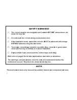
WARNING

1. The circuit under test 

must

be de-energized and

isolated before insulation or continuity tests are
made.

2. When capacitive circuits have been tested allow a

suitable time to elapse before disconnecting the
test leads, for the circuit to discharge.

3. Instruments used in dusty environments should be

stripped and cleaned periodically.

4. Do not leave the instrument exposed to direct heat

from the sun for long periods.

5. The instrument circuit contains a static sensitive

device. If the instrument casing is opened for any
reason (this will automatically invalidate any
warranty covering the instrument), care must be
exercised in handling the printed circuit board.
This should be done in accordance with DEF
STAN 59-98 and BS 5783 specifications for
handling electrostatic sensitive devices. 
Printed circuit boards containing such devices are
identified either by a yellow warning label or by a
yellow legend and a large yellow dot on the p.c.b.
(Initially the  dot may not be included.)

PRELIMINARY CHECKS

Inspect the test leads to see that they have good
unbroken insulation. Connect the red and black leads,
terminated with the clips, to the red (+) and black (–)
terminal sockets respectively in the side of the
instrument case. Leave the leads coiled or twisted
together, but ensure that their clips are not touching
anything. Set the slider switch to the ‘M

’ position.

Turn the generator handle at approximately 160 r.p.m.
and observe the meter pointer, it should rest over the

’ (infinity) position on the scale. If it does not the test

leads may be faulty and should be inspected more
closely for damage. Replace them if necessary.

Connect the test lead clips together and turn the
generator handle again, the meter should read zero. 
If it indicates infinity or a high resistance value the
leads may be open circuit and should be inspected
further, replace if necessary. Shorting the leads
together and obtaining a zero reading also proves that
the instrument is working.

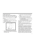
To check that the fuse in the continuity circuit is intact,
leave the test leads connected together and set the
slider switch to the ‘

’ position. Turn the generator

handle again, the reading obtained should be zero (or
very nearly so). If the reading is beyond full scale on
the ‘

’ range the fuse has ruptured and should be

replaced.

8

Summary of Contents for WM6

Page 1: ...M WM6 Wee Megger Tester User Guide Guide de l utilisateur Gebrauchsanleitung Gu a del usuario...

Page 2: ...t leads Test leads including prods and crocodile clips must be in good order clean and having no broken or cracked insulation Replacement fuses must be of the correct type and rating Refer also to pag...

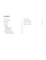
Page 3: ...ation 8 Warning 8 Preliminary checks 8 Fuse replacement 8 Insulation testing 9 Continuity testing 9 Using the Insulation Tester 10 Preventive maintenance 10 Insulation Testing concepts 11 Mode d Emplo...

Page 4: ...om 0 to 200 M Two shrouded sockets are provided in the side of the case for the test leads and a slider switch selects either insulation or continuity tests M or The case is robust made of ABS plastic...

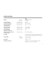
Page 5: ...hort Circuit continuity range 55 mA approx Voltage Stability insulation range 1 160 r p m to 240 r p m Ripple Content at 160 r p m insulation range 500 mV pk pk approx on Open Circuit Accuracy 1 5 mm...

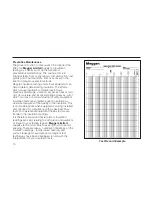
Page 6: ...ECIFICATION Fuse 1 A 20 x 5 mm ceramic Dimensions 131 x 98 x 61 mm 51 8 x 37 8 x 23 8 in Weight 650 g 1 lb 7 oz Terminal Voltage Characteristics 6 WM6 Terminal voltage volts d c Resistance under test...

Page 7: ...t including shrouded crocodile clips User Guide Part No 6171 685 Test Record Card 5 supplied Part No 6172 111 AVAILABLE AS AN OPTIONAL EXTRA A test and carry case with a special compartment for test l...

Page 8: ...see that they have good unbroken insulation Connect the red and black leads terminated with the clips to the red and black terminal sockets respectively in the side of the instrument case Leave the le...

Page 9: ...ce is charged up to the output voltage of the tester If several successive readings of are obtained connect the two further ends of the test leads together and turn the generator handle A zero reading...

Page 10: ...which can arise on most industrial or utility equipment Insulation tests are sometimes used in isolation as absolute measures of the quality of the insulation This is most appropriate when equipment...

Page 11: ...sulation material b A current flowing along conduction paths over the surface of the insulation material As the total current depends upon the time for which the voltage is applied Ohm s Law theoretic...

Page 12: ...ter les pinces crocodiles et actionner nouveau la manivelle L aiguille de l indicateur doit se placer sur le z ro de l chelle En cas d indication de r sistance de valeur lev e ou position les cordons...

Page 13: ...anch s ni coup s et que les mesures d isolement effectu es sont en fait correctes Les circuits capacitifs sont automatiquement d charg s dans l appareil quand on arr te de tourner la manivelle L aigui...

Page 14: ...nicht der Fall k nnen die Testkabel defekt sein und sie sind genauer auf eine Besch digung zu untersuchen Die Kabel erforderlichenfalls ersetzen Die Kabelklemmen bzw Enden verbinden und die Generator...

Page 15: ...en Dabei sollte man nun eine Nullablesung erhalten als Gegenpr fung daf r da die Kabel nicht getrennt oder unter brochen sind und Isolationswiderstandsablesungen somit korrekt sind Kapazitive Schaltun...

Page 16: ...M Girar la manivela del generador en aproximadamente 160 r p m y observar la aguja del indicador la cual deber permanecer sobre la posici n infinito de la escala Si esto no es asi puede que est n ave...

Page 17: ...girar la manivela del generador Deber obtenerse una lectura cero con lo cual se comprueba por partida doble que las sondas no est n desconectadas o rotas y que por consiguiente son correctas las lect...

Page 18: ...meter Adjustment for Conditions for adjustment 1 R15 scale 10 M mark a switched to M b 10 M 500 V rating resistor across b terminals 2 R16 scale 0 M mark a switched to M b short circuit across termina...

Page 19: ...ntact Megger Limited or Megger Archcliffe Road Valley Forge Corporate Center Dover 2621 Van Buren Avenue Kent CT17 9EN Norristown PA 19403 England U S A Tel 44 0 1304 502243 Tel 1 610 676 8579 Fax 44...

Page 20: ......

Page 21: ......
Page 22: ...Dover Kent CT17 9EN ENGLAND T 44 0 1 304 502101 F 44 0 1 304 207342 Megger Valley Forge Corporate Center 2621 Van Buren Avenue Norristown PA 19403 USA T 1 610 676 8500 F 1 610 676 8610 Megger 4271 Bro...

Reviews: