46
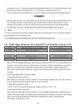
As shown in Fig. 4-1, t1 is the jog acceleration and deceleration time (P11.16) of actual running. t2 is the
jog time and t3 is the jog interval time (P11.17). f is the jog running frequency (P11.18).
The jog acceleration and deceleration time t
1
of actual running is determined by the following equation:
15
.
02
18
.
11
16
.
11
1
t
P
P
P
×
=
The jog interval time (P11.17) is the waiting time interval from canceling the jog command last time to the
next valid jog command. In the interval, the jog command will not make the drive operate. The drive
operates at zero frequency of the non-output. If the jog command persists, the jog command will be
executed after the interval. The jog command is executed immediately after the jog interval.
Note
1. The jog running starts and stops according to start mode 0 and stop mode 0. The unit for the acceleration
and deceleration time is second by default.
2. The operation panel, control terminal and serial port can perform the jog control.
4.6 Multi-stage reference and simple PLC parameters (Group P13)
……
When it is the multi-stage frequency, its setting range can be set as 0.0%~100.0%, corresponding to zero
frequency to the maximum frequency. When used as multi-speed operation independently, its operating
direction is controlled by the running terminal. When the running terminal is forward output (FWD),
operate the forward frequency. When the running terminal is reverse output (REV), operate the reverse
frequency.
P13.00 Multi-stage reference property setting:
0: Multi-stage frequency reference 1
When working in multi-stage frequency reference 1, the multi-stage speed reference can meet customer
up to 16 segments speed settings according to the input terminals.
1: Multi-stage closed loop reference
-100.0% ~100.0% corresponds to closed-loop voltage reference of -10V~+ 10V.
2: Multi-stage frequency reference 2
When working in multi-stage frequency reference 2, the multi-stage speed reference only accepts input
signals in the following table, multi-stage speed setting display and setting also as shown in the following
table, in which 0 represents that the multi-function terminal input is invalid, 1 represents that
multi-function terminal input is valid.
Reserved
P13.16
~
P13.46
Multi-stage reference 5
-100.0~100.0%(100.0%)
P13.15
Multi-stage reference 1
-100.0~100.0%(30.0%)
P13.01
Multi-stage reference property setting
0~3(0)
P13.00


