O
PTO
C
ON
R
EFERENCE
F-3
S
w
it
ch
S
et
tin
g
s
S
w
itc
h
es
S
2
, S
3
Switches S2, S3
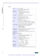
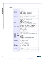
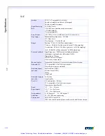
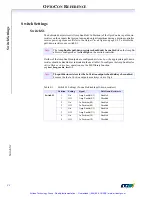
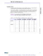
To configure the User I/O opto-isolation circuitry as inputs or outputs, use switches S2 and S3.
To set the input and output directions, use the settings in the next table.
The directions set with the switches should match those set on the controller using the MEI li-
brary function
init_boot_io(...)
, so that the OptoCon and the DSP controller are configured iden-
tically at power-up. After using
init_boot_io(...)
to configure a port’s direction, do not use
init_io(...)
to reconfigure the port’s direction.
Warning!
You can only use the switch settings shown in the table.
Other switch settings may damage the OptoCon circuits.
Table F-2 Switch S2/S3 Settings (To configure User I/O as inputs or outputs)
Position
Port A/B Input
Port C Input
Port A/B Input
Port C Output
Port A/B Output
Port C Input
Port A/B Output
Port C Output
Switch S2
1
Off
Off
On
On
2
Off
On
Off
On
3
Off
Off
On
On
4
Off
Off
On
On
Switch S3
1
Off
Off
On
On
2
Off
Off
On
On
3
Off
Off
On
On
4
Off
Off
On
On
5
Off
On
Off
On
6
Off
On
Off
On
7
Off
On
Off
On
8
Off
On
Off
On
Artisan Technology Group - Quality Instrumentation ... Guaranteed | (888) 88-SOURCE | www.artisantg.com


