O
PTO
C
ON
R
EFERENCE
F-4
In
st
a
ll
a
ti
o
n
S
w
it
ch
es
S
2
,
S
3
Installation
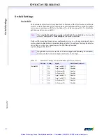
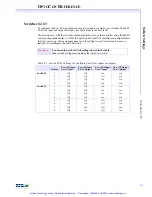
Before connecting any cables or wires to the OptoCon, you must correctly set the switches
as described in the preceding section.
Only the switch settings shown in the table are al-
lowed!
Other switch settings may cause damage to the OptoCon module and the DSP con-
troller.
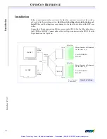
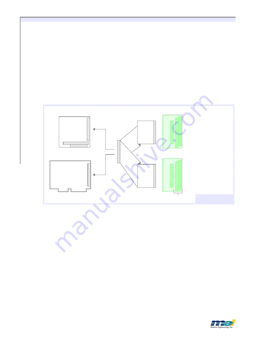
Connect the 100-pin connector on MEI accessory cable CBL-100 to the 100-pin header on
the LC/DSP or 104/DSP. Connect either of the two 50-pin connectors on the CBL-100 to the
50-pin header on the OptoCon.
OptoCon Cabling
O
PTO
C
ON
104/DSP
O
PTO
C
ON
LC/DSP
CBL-100
Motor, Encoder & Dedicated
I/O for Axes (2, 3)
User I/O PB0-PB5,
PC4-PC7
Motor, Encoder & Dedicated
I/O for Axes (0, 1)
User I/O PA0-PA5,
PC0-PC3
O
R
100 pin
header
100 pin
header
50 pin
50 pin
Screw Terminal
Connections
100 pin
connector
Artisan Technology Group - Quality Instrumentation ... Guaranteed | (888) 88-SOURCE | www.artisantg.com

