O
PTO
C
ON
R
EFERENCE
F-8
In
st
a
ll
a
ti
o
n
S
ch
em
a
ti
cs
Schematics
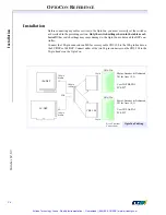
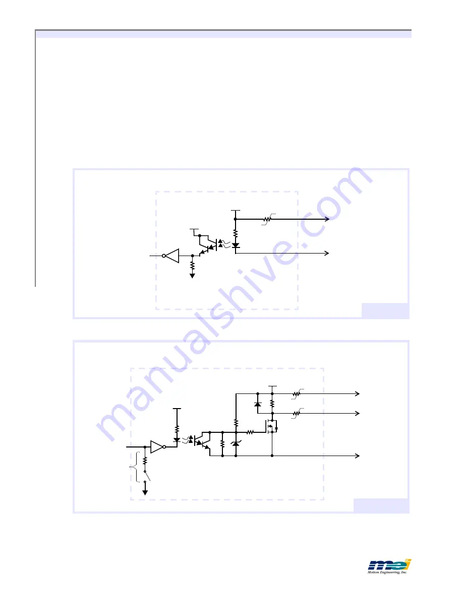
All OptoCon input and output circuits are electrically identical. To program the User I/O sig-
nals (OptoCon 1: PA0-5, PC0-3; OptoCon 2: PB0-5, PC4-7) as inputs or outputs, use the
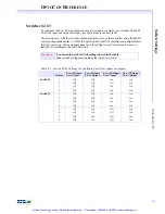
switches S2 and S3 on the OptoCon and in conjunction with the MEI library function
init_boot_io(...)
on the motion controller. After using
init_boot_io(...)
to configure a port’s di-
rection, do not use
init_io(...)
to reconfigure the port’s direction.
The Dedicated I/O signals (Amp Enable, In Position, Positive Limit, Negative Limit, Home
and Fault)
cannot be reconfigured
. All of the I/O signals share a common supply, (
V_USER
/
USER_GND)
, which is fused at 1 amp. Additionally, each individual output is fused at 1 amp.
2.7K
Vcc
V_Opto
P2-2
P2-27 - P2-34,
P2-39 - P2-48
Fuse
1A, 60V
V_USER
Input
To
Controller
T
YPICAL
I
NPUT
C
IRCUIT
Input Circuit
Note:
V_OPTO
is shared by all input
and output circuits in the OptoCon.
10K
V_Opt
Vcc
P2-35 - P2-48
P2-18, P2-50
Fuses
1A, 60V
V_USER
From
Controller
T
YPICAL
O
UTPUT
C
IRCUIT
Output Circuit
S1
On Amp Enable
& In_Position
signals only
Output
USER_GN
P2-2
Note:
V_OPTO
is shared by all input
and output circuits in the OptoCon.
1.5K
Artisan Technology Group - Quality Instrumentation ... Guaranteed | (888) 88-SOURCE | www.artisantg.com

