


O
PTO
C
ON
R
EFERENCE
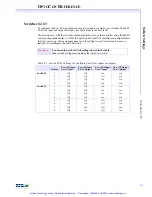
F-13
C
ir
cu
it
E
x
a
m
p
le
s
C
o
n
n
ec
t a
n
O
p
to
C
o
n
O
u
tp
u
t t
o
a
R
el
a
y
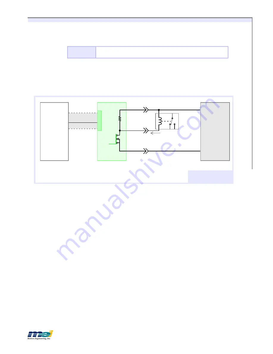
Connect an OptoCon Output to a Relay
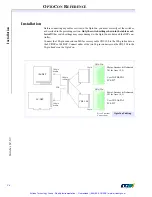
The next figure shows how to drive a relay using one of the User I/O (PA0) signals from the
motion controller via the OptoCon. This circuit can be used with
any
of the OptoCon outputs.
When PA0 is set ‘low’, the relay is energized. For the OptoCon to work correctly in this con-
figuration, I
sink
must be smaller than the maximum “On” state
output current
for the OptoCon
(250 mA). If this condition is not met, the relay may not switch. To calculate I
sink
:
I
sink
≅
(V – V
DS
) / R
C
V
=
Amplifier logic
power
supply voltage
V
DS
=
OptoCon “On” state
output voltage
, V
DS
< 0.25V
R
C
=
Relay coil resistance
Warning!
You must set S1 correctly for “Active High” or “Active Low” Amp
Enable Operation.
(see
Switch Settings
on F-2)
10K
LC/DSP
104/DSP
P2-2
+V
Common
CBL-100
PA0
P2-35
P1
OptoCon
OptoCon Output to
A Relay
Power Supply
(+5V to +24V)
P2-18,50
Relay
I
Sink
For output circuitry, see
schematics on page F-8.
Artisan Technology Group - Quality Instrumentation ... Guaranteed | (888) 88-SOURCE | www.artisantg.com


