C
ONFIGURE
& I
NSTALL
B
OARD
2-11
S
T
D
L
o
ca
te
S
w
itc
h
es
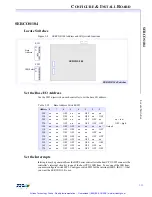
STD
Locate Switches
Figure 2-3
STD Address and IRQ Switch Locations
Set Base I/O Address
Use the SW1 dipswitch on each controller to set the base I/O address.
Set the Interrupts
Interrupts may be generated from the DSP Series controller to the host CPU. SW2 connects the
controller’s interrupt circuitry to one of the host CPU’s IRQ lines.
To use one of the IRQ lines, you must configure switch SW2. Configure switch SW2 for the
interrupt (IRQ2, IRQ3, ...) that you want the STD to use.
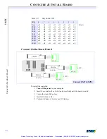
Table 2-5
Base Address Switch SW1
Address 8
7
6
5
4
3
2
1
240
on
on
OFF
on
on
OFF
on
on
250
on
on
OFF
on
on
OFF
on
OFF
260
on
on
OFF
on
on
OFF
OFF
on
on = low
270
on
on
OFF
on
on
OFF
OFF
OFF
OFF = high
300
on
on
OFF
OFF
on
on
on
on
Default
310
on
on
OFF
OFF
on
on
on
OFF
320
on
on
OFF
OFF
on
on
OFF
on
330
on
on
OFF
OFF
on
on
OFF
OFF
340
on
on
OFF
OFF
on
OFF
on
on
350
on
on
OFF
OFF
on
OFF
on
OFF
360
on
on
OFF
OFF
on
OFF
OFF
on
370
on
on
OFF
OFF
on
OFF
OFF
OFF
O
N
O
N
IRQ Select
SW 2
Base Address
SW 1
STD
STD Switches
Artisan Technology Group - Quality Instrumentation ... Guaranteed | (888) 88-SOURCE | www.artisantg.com


