C
ONFIGURE
& I
NSTALL
B
OARD
2-14
S
E
R
C
O
S
/S
T
D
C
o
n
n
ec
t
C
a
b
le
s/
In
se
rt
B
o
a
rd
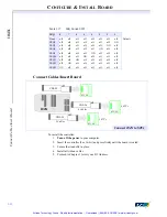
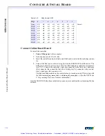
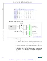
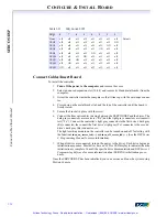
Connect Cables/Insert Board
To install the controller:
1.
Turn off the power to the STD card cage
and remove the card clamp.
2. Select an unused slot (STD/32 or STD/80).
3. Insert the controller and press firmly until the board is seated in the card-edge connec-
tor.
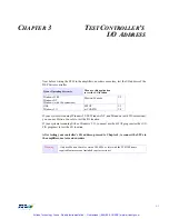
4. Proceed to Chapter 3 to test your I/O Address,
then return to Step 4
.
5. Connect the fiber optic cables in a ring between the SERCOS/STD and the drives. The
dark gray connectors are receivers (“Rx”) and the light gray connectors are transmit-
ters (“Tx”). Connect the controller’s light gray connector to the first drive’s dark gray
(Rx) connector, the connect the first drive’s light gray (Tx) connector to the second
drive’s dark gray (Rx) connector, etc.
The light-emitting module on the controller can be turned on and off for testing with
the functions
turn_on_sercos_led(…)
and
turn_off_sercos_led(…)
.
(See the
DSP Series
C Programming Reference
for more information.)
6. When all drives are connected, turn on the power to the drives. Each drive begins an
initialization sequence. Most drives have an LCD or LED display to indicate when the
initialization is complete. Consult the specific drive documentation and chapter 6
of
DSP Series C Programming Reference
for more information about SERCOS initial-
ization procedures.
Once the SERCOS/STD has been initialized, you can exercise and tune the system using Mo-
tion Console.
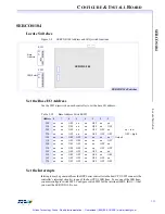
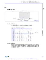
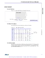
Table 2-8
IRQ Switch SW2
IRQ
4
3
2
1
None
off
off
off
off
Default
IRQX*
off
off
off
ON
*
only supported by the STD-32 bus
INTRQ3*
off
off
ON
off
INTRQ
ON
off
off
off
INTRQ1
off
ON
off
off
Artisan Technology Group - Quality Instrumentation ... Guaranteed | (888) 88-SOURCE | www.artisantg.com


